Книга: Introduction to Microprocessors and Microcontrollers
Shift registers
Shift registers
These are a variation on the register theme. They still consist of group of flip-flops but the interconnections have been changed. Have a look at the arrangement in Figure 6.7 and see if you can guess the likely outcome.
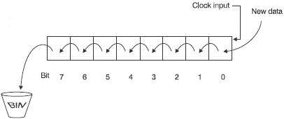
Figure 6.7 A shift-left register
This is called a shift register because the data is shifted from one flipflop to the next each time the clock pulse occurs. Specifically, the one shown is a shift left register because each bit moves one place to the left on each clock pulse. All the bits move at the same time. The last one in bit 7 drops off the end and is lost while at the other end, a new bit is entered into bit 0.
In Figure 6.8, the register has been loaded with the binary equivalent of 3610 or 24H and a series of zeros has been chosen to be loaded at the bit 0 end.
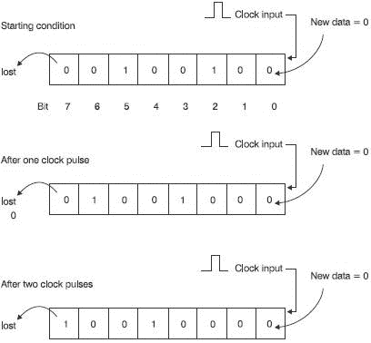
Figure 6.8 A shift-left register in action
Follow the sequence through and in particular note what happens to the numbers stored:
1 After one clock pulse, all the bits will have moved one place to the left. A new ‘0’ will have entered bit 0 and the last, which was in bit 7, will have fallen off the end of the world. The bits stored at this time are 01001000 and the numerical value is 48H or, in denary, 7210. Notice how shifting the bits to the left has multiplied the value by 2.
2 After eight clock pulses, all the existing data in the register will have been flushed out and refilled with zeros. The register will hold the number zero so there is a limit to how many times we can multiply by shifting the register.
3 After 5000 clock pulses, it is still full of zeros. Admittedly, they will be new zeros that have replaced the others but that will not make any difference.
What happens if we don’t apply any input data to enter bit 0?
If the input connection is simply left unconnected, there will be no voltage information coming in to the first flip-flop. The input is said to be ‘floating’ and will assume some voltage which may be low or high. As the clock pulses are applied this may well result in random data entering the register. Random data is of no help to anyone so we normally overcome this problem by building in a bias in the design of the register to make it have a tendency to move towards one logic level rather than the other. It is up to the manufacturer but most floating inputs will float high and enter ones.
The shift register considered has been a shift-left register, which means that the information is fed in at the right-hand end and moves progressively towards the left along the register until it drops off the end.
By re-arranging the register, it is easy to produce a shift-right register as in Figure 6.9. This has all the same properties except it shifts data towards the right and divides the number by two each time the clock pulse is entered. Compare Figures 6.7 and 6.9.
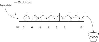
Figure 6.9 A shift-right register
A real world use for a shift register
It is interesting that a shift register can perform simple multiplication and division but it can do many jobs that are more interesting.
One example would be automatic checking of inputs. In Figure 6.10 it is controlling an automatic ticket dispenser. The customer inserts some money and presses any button of the eight available to obtain the ticket required – but which button was pressed?
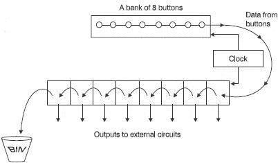
Figure 6.10 Using a shift register
As a button is pressed the voltage output can be designed to change from logic 0 to logic 1 so to start with, we can assume no buttons are pressed and the response from each button is zero. Along comes a customer who, having read the instructions, inserted some money and re-read the instructions and stared at the buttons, eventually decides to press a button.
Pressing a button generates a burst of eight clock pulses and the value of each button is loaded into the shift register. Once the button has been pressed the zeros and ones corresponding to each of the buttons is loaded into the shift register. The output from each button is made available to external circuits and one such circuit will be activated and a ticket will drop down the chute.
For how long would the customer have to press the button?
The microprocessor is amazingly fast compared with us. If we feel the temperature of a piece of metal and it is too hot, we immediately take our hand off. But how long did this take? For most people the time to think and then respond would be about one-tenth of a second. In sport, it means that the person at the receiving end must use body movement or magic to predict what is going to happen. Waiting to respond to the flight of the ball will make them too late. Most people would therefore press a button for at least 0.1 s. So what can the microprocessor do in the same 0.1 s? A modern microprocessor can check a button in about 0.25 µs or 0.25 millionths of a second. In other words, it can check about 4 000 000 buttons in a second.
We have a best response time of 0.1 s. The microprocessor has a response time of about 0.25 µs. This means than the microprocessor lives at a speed of about 400 000 times faster than us. Can you imagine how we would feel faced with a creature called a ‘Waitabit’ that moves 400 000 times slower than us? It would take 11 hours to press the button. After all that effort, it may run off at 3 cm/h (1.2 in/h) to spend 11 years having a cup of coffee. By way of compensation, it may well live for 28 million years!
- A flip-flop or bistable
- A register
- Shift registers
- Rotate registers
- Memories
- RAM
- Accessing memory
- Two types of RAM
- Memory organization
- Three types of ROM
- Pin layout of an EPROM
- Pin layout of a SRAM
- Pin layout of a DRAM
- Some more memories that don’t fit into the general pattern
- Memory maps
- Quiz time 6
