Книга: Introduction to Microprocessors and Microcontrollers
Appendix B: PIC 16CXXX instruction set
Appendix B: PIC 16CXXX instruction set
| Syntax | Description | Status affected |
|---|---|---|
| ADDLW k | The contents of the W register are added to an 8-bit number and the result put in the W reg. | C, DC, Z |
| ADDWF f,d | Add the contents of the W and f registers. If d=0 the result goes to W. If d=1 the result goes to the f register | C, DC, Z |
| ANDLW k | The contents of the W register are ANDed with an 8-bit number and the result put in the W reg. | Z |
| ANDWF f,d | AND w with reg f. If d=0 the result goes to W. If d=1 the result goes to the f register | Z |
| BCF f,b | Bit b in reg f is cleared | |
| BSF f,b | Bit b in reg f is set | |
| BTFSS f,b | If bit b in reg f=0, the next instruction in executed. If it is 1 the next instr. is replaced with a NOP | 1 or 2 cycles |
| BTFSC f,b | If bit b in reg f=1, the next instruction in executed. If it is 0 the next instr. is replaced with a NOP | 1 or 2 cycles |
| CALL k | Call subroutine. Return address (PC+1) is pushed onto stack. The 11-bit immediate address is loaded into PC bits 1:0 The upper bits of the PC are loaded from PCLATH 4:3. | 2 cycle |
| CLRF | f Register f is cleared and Z flag is set. | Z |
| CLRW | Register W is cleared and Z flag is set. | Z |
| CLRWDT | Resets watchdog timer and watchdog prescaler | TO, PD |
| COMF f,d | Contents of ‘f’ are complemented (0?1, 1?0) If d=0 the result goes to W. If d=1 the result goes to f | Z |
| DECF f,d | Contents of ‘f’ reduced by 1. If d=0 the result goes to W. If d = 1 the result goes to f | Z |
| DECFSZ f,d | Contents of ‘f’ reduced by 1. if d=0 the result goes to W. If d=1 the result goes to f. If result = 1, the next instruction in executed. If it is 0 the next instr. is replaced with a NOP | 1 or 2 cycles |
| GOTO k | The 11-bit immediate address is loaded into PC bits <10:0>. The upper bits of the PC are loaded from PCLATH <4:3>. | |
| INCF f,d | If d=0 the result goes to W. If d=1, result goes to f. | |
| INCFSZ f,d | Contents of ‘f’ incremented. If d=0 the result goes to W. If d=1 the result goes to f. If rfesult = 1, the next instruction is executed. If it is 0 the next instr. is replaced with a NOP | 1 or 2 cycles |
| IORLW k | The contents of the W register are ANDed with an 8-bit number and the result put in the W reg. | Z |
| IORFWF f,d | The contents of the W register are Inclusive ORed with reg. F. If d=1 resujlt goes back into f | |
| MOVF f,d | If d=0, contents of f goes to W reg. If d=1 it goes to f | Z |
| MOVLW k | The 8-bit number k goes into W. | |
| MOVWF f | Moves data from W register to f register | |
| NOP | Does nothing – just a time waster (one cycle period) | |
| RETFIE | Return from interrupt. Top of stack?PC, 1?GIE | 2 cycle |
| RETLW k | W reg loaded with number , return address?PC | 2 cycle |
| RETURN | Return from subroutine. Return address?PC | 2 cycle |
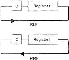
| RLF f,d | Contents of ‘f’ are rotated left one bit via the carry flag. If d=0 the result goes to W. result goes back to f. See fig. below | C |
| SLEEP | Powerdown status bit PD is cleared, Timeout status bit TO is set. WDT and prescaler are cleared, oscillator stops and controller goes to sleep. | TO, PD |
| SUBLW k | W register subtracted from the number k, result goes into W reg. (2’s complement method) | C, DC, Z |
| SUBWF f,d | W register subtracted from the register f. If d=0 the result goes to W. If d=1 the result goes to f. (2’s complement method) | C, DC, Z |
| SWAPF f,d | Upper and lower nibbles of f are exchanged. If d=0 the result goes to W. If d=1 the result goes to f. | |
| XORLW k | W register contents XOR’ed with the number k, result goes into W reg. | Z |
| XORWF f,d | W register contents XOR’ed with the register f, if d=0 the result goes to W. If d=1 the result goes to f | Z |

Оглавление статьи/книги
- Preface
- 1. Basic microprocessor systems
- 2. Binary – the way micros count
- 3. Hexadecimal – the way we communicate with micros
- 4. How micros calculate
- 5. An introduction to logic gates and their uses
- 6. Registers and memories
- 7. A microprocessor-based system
- 8. A typical 8-bit microprocessor
- 9. Programming – using machine code and assembly
- 10. High-level languages
- 11. The development of microprocessors and microcontrollers
- 12. The Pentium family
- 13. The PowerPC
- 14. The Athlon XP
- 15. Microcontrollers and how to use them
- 16. Using a PIC microcontroller for a real project
- 17. Interfacing
- 18. Test equipment and fault-finding
- Appendix A: Special function register file
- Appendix B: PIC 16CXXX instruction set
- Further reading
- Quiz time answers
- Содержание книги
- Популярные страницы
Похожие страницы
- 8.5.2 Typical Condition Variable Operations
- SET TERM больше не нужен в isql
- Chapter 8. Saving and restoring large rule-sets
- Appendix A. Detailed explanations of special commands
- Appendix B. Common problems and questions
- Appendix C. ICMP types
- Appendix D. TCP options
- Appendix E. Other resources and links
- Appendix F. Acknowledgments
- Appendix G. History
- Appendix H. GNU Free Documentation License
- Appendix I. GNU General Public License


