Êíèãà: Advanced PIC Microcontroller Projects in C
2.1.12 Interrupts
Ðàçäåëû íà ýòîé ñòðàíèöå:
2.1.12 Interrupts
An interrupt is an event that requires the CPU to stop normal program execution and then execute a program code related to the event causing the interrupt. Interrupts can be generated internally (by some event inside the chip) or externally (by some external event). An example of an internal interrupt is a timer overflowing or the A/D completing a conversion. An example of an external interrupt is an I/O pin changing state.
Interrupts can be useful in many applications such as:
• Time critical applications. Applications which require the immediate attention of the CPU can use interrupts. For example, in an emergency such as a power failure or fire in a plant the CPU may have to shut down the system immediately in an orderly manner. In such applications an external interrupt can force the CPU to stop whatever it is doing and take immediate action.
• Performing routine tasks. Many applications require the CPU to perform routine work at precise times, such as checking the state of a peripheral device exactly every millisecond. A timer interrupt scheduled with the required timing can divert the CPU from normal program execution to accomplish the task at the precise time required.
• Task switching in multi-tasking applications. In multi-tasking applications, each task may have a finite time to execute its code. Interrupt mechanisms can be used to stop a task should it consume more than its allocated time.
• To service peripheral devices quickly. Some applications may need to know when a task, such as an A/D conversion, is completed. This can be accomplished by continuously checking the completion flag of the A/D converter. A more elegant solution would be to enable the A/D completion interrupt so the CPU is forced to read the converted data as soon as it becomes available.
The PIC18F452 microcontroller has both core and peripheral interrupt sources. The core interrupt sources are:
• External edge-triggered interrupt on INT0, INT1, and INT2 pins.
• PORTB pins change interrupts (any one of the RB4–RB7 pins changing state)
• Timer 0 overflow interrupt
The peripheral interrupt sources are:
• Parallel slave port read/write interrupt
• A/D conversion complete interrupt
• USART receive interrupt
• USART transmit interrupt
• Synchronous serial port interrupt
• CCP1 interrupt
• TMR1 overflow interrupt
• TMR2 overflow interrupt
• Comparator interrupt
• EEPROM/FLASH write interrupt
• Bus collision interrupt
• Low-voltage detect interrupt
• Timer 3 overflow interrupt
• CCP2 interrupt
Interrupts in the PIC18F family can be divided into two groups: high priority and low priority. Applications that require more attention can be placed in the higher priority group. A high-priority interrupt can stop a low-priority interrupt that is in progress and gain access to the CPU. However, high-priority interrupts cannot be stopped by low-priority interrupts. If the application does not need to set priorities for interrupts, the user can choose to disable the priority scheme so all interrupts are at the same priority level. High-priority interrupts are vectored to address 00008H and low-priority ones to address 000018H of the program memory. Normally, a user program code (interrupt service routine, ISR) should be at the interrupt vector address to service the interrupting device.
In the PIC18F452 microcontroller there are ten registers that control interrupt operations. These are:
• RCON
• INTCON
• INTCON2
• INTCON3
• PIR1, PIR2
• PIE1, PIE2
• IPR1, IPR2
Every interrupt source (except INT0) has three bits to control its operation. These bits are:
• A flag bit to indicate whether an interrupt has occurred. This bit has a name ending in …IF
• An interrupt enable bit to enable or disable the interrupt source. This bit has the name ending in …IE
• A priority bit to select high or low priority. This bit has a name ending in …IP
RCON Register
The top bit of the RCON register, called IPEN, is used to enable the interrupt priority scheme. When IPEN = 0, interrupt priority levels are disabled and the microcontroller interrupt structure is similar to that of the PIC16 series. When IPEN = 1, interrupt priority levels are enabled. Figure 2.46 shows the bits of register RCON.
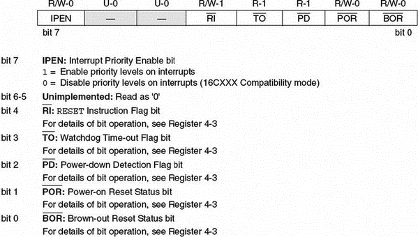
Figure 2.46: RCON register bits
Enabling/Disabling Interrupts — No Priority Structure
When the IPEN bit is cleared, the priority feature is disabled. All interrupts branch to address 00008H of the program memory. In this mode, bit PEIE of register INTCON enables/disables all peripheral interrupt sources. Similarly, bit GIE of INTCON enables/disables all interrupt sources. Figure 2.47 shows the bits of register INTCON.
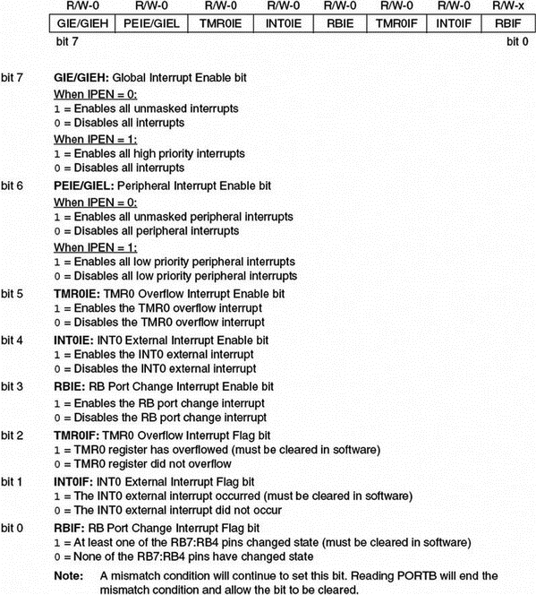
Figure 2.47: INTCON register bits
For an interrupt to be accepted by the CPU the following conditions must be satisfied:
• The interrupt enable bit of the interrupt source must be enabled. For example, if the interrupt source is external interrupt pin INT0, then bit INT0IE of register INTCON must be set to 1.
• The interrupt flag of the interrupt source must be cleared. For example, if the interrupt source is external interrupt pin INT0, then bit INT0IF of register INTCON must be cleared to 0.
• The peripheral interrupt enable/disable bit PEIE of INTCON must be set to 1 if the interrupt source is a peripheral.
• The global interrupt enable/disable bit GIE of INTCON must be set to 1.
With an external interrupt source we normally have to define whether the interrupt should occur on the low-to-high or high-to-low transition of the interrupt source. With INT0 interrupts, for example, this is done by setting/clearing bit INTEDG0 of register INTCON2.
When an interrupt occurs, the CPU stops its normal flow of execution, pushes the return address onto the stack, and jumps to address 00008H in the program memory where the user interrupt service routine program resides. Once the CPU is in the interrupt service routine, the global interrupt enable bit (GIE) is cleared to disable further interrupts. When multiple interrupt sources are enabled, the source of the interrupt can be determined by polling the interrupt flag bits. The interrupt flag bits must be cleared in the software before reenabling interrupts to avoid recursive interrupts. When the CPU has returned from the interrupt service routine, the global interrupt bit GIE is automatically set by the software.
Enabling/Disabling Interrupts — Priority Structure
When the IPEN bit is set to 1, the priority feature is enabled and the interrupts are grouped into two: low priority and high priority. Low-priority interrupts branch to address 00008H and high-priority interrupts branch to address 000018H of the program memory. Setting the priority bit makes the interrupt source a high-priority interrupt, and clearing this bit makes the interrupt source a low-priority interrupt.
Setting the GIEH bit of INTCON enables all high-priority interrupts that have the priority bit set. Similarly, setting the GIEL bit of INTCON enables all low-priority interrupts (the priority is bit cleared).
For a high-priority interrupt to be accepted by the CPU, the following conditions must be satisfied:
• The interrupt enable bit of the interrupt source must be enabled. For example, if the interrupt source is external interrupt pin INT1, then bit INT1IE of register INTCON3 must be set to 1.
• The interrupt flag of the interrupt source must be cleared. For example, if the interrupt source is external interrupt pin INT1, then bit INT1IF of register INTCON3 must be cleared to 0.
• The priority bit must be set to 1. For example, if the interrupt source is external interrupt INT1, then bit INT1P of register INTCON3 must be set to 1.
• The global interrupt enable/disable bit GIEH of INTCON must be set to 1.
For a low-priority interrupt to be accepted by the CPU, the following conditions must be satisfied:
• The interrupt enable bit of the interrupt source must be enabled. For example, if the interrupt source is external interrupt pin INT1, then bit INT1IE of register INTCON3 must be set to 1.
• The interrupt flag of the interrupt source must be cleared. For example, if the interrupt source is external interrupt pin INT1, then bit INT1IF of register INTCON3 must be cleared to 0.
• The priority bit must be cleared to 0. For example, if the interrupt source is external interrupt INT1, then bit INT1P of register INTCON3 must be cleared to 0.
• Low-priority interrupts must be enabled by setting bit GIEL of INTCON to 1.
• The global interrupt enable/disable bit GIEH of INTCON must be set to 1.
Table 2.12 gives a listing of the PIC18F452 microcontroller interrupt bit names and register names for every interrupt source.
Table 2.12: PIC18F452 interrupt bits and registers
| Interrupt source | Flag bit | Enable bit | Priority bit |
|---|---|---|---|
| INT0 external | INT0IF | INT0IE | – |
| INT1 external | INT1IF | INT1IE | INT1IP |
| INT2 external | INT2IF | INT2IE | INT2IP |
| RB port change | RBIF | RBIE | RBIP |
| TMR0 overflow | TMR0IF | TMR0IE | TMR0IP |
| TMR1 overflow | TMR1IF | TMR1IE | TMR1IP |
| TMR2 match PR2 | TMR2IF | TMR2IE | TMR2IP |
| TMR3 overflow | TMR3IF | TMR3IE | TMR3IP |
| A/D complete | ADIF | ADIE | ADIP |
| CCP1 | CCP1IF | CCP1IE | CCP1IP |
| CCP2 | CCP2IF | CCP2IE | CCP2IP |
| USART RCV | RCIF | RCIE | RCIP |
| USART TX | TXIF | TXIE | TXIP |
| Parallel slave port | PSPIF | PSPIE | PSPIP |
| Sync serial port | SSPIF | SSPIE | SSPIP |
| Low-voltage detect | LVDIF | LVDIE | LVDIP |
| Bus collision | BCLIF | BCLIE | BCLIP |
| EEPROM/FLASH write | EEIF | EEIE | EEIP |
Figures 2.48 to 2.55 show the bit definitions of interrupt registers INTCON2, INTCON3, PIR1, PIR2, PIE1, PIE2, IPR1, and IPR2.
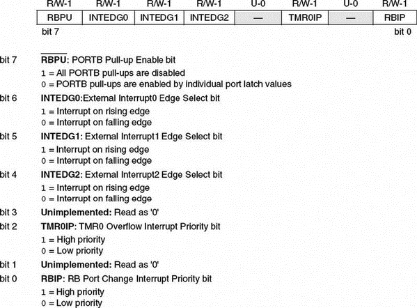
Figure 2.48: INTCON2 bit definitions
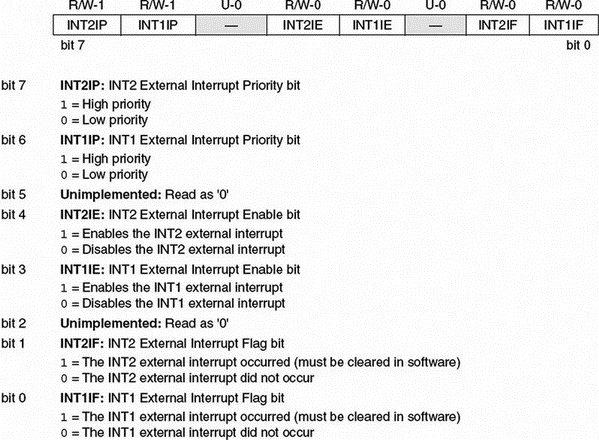
Figure 2.49: INTCON3 bit definitions
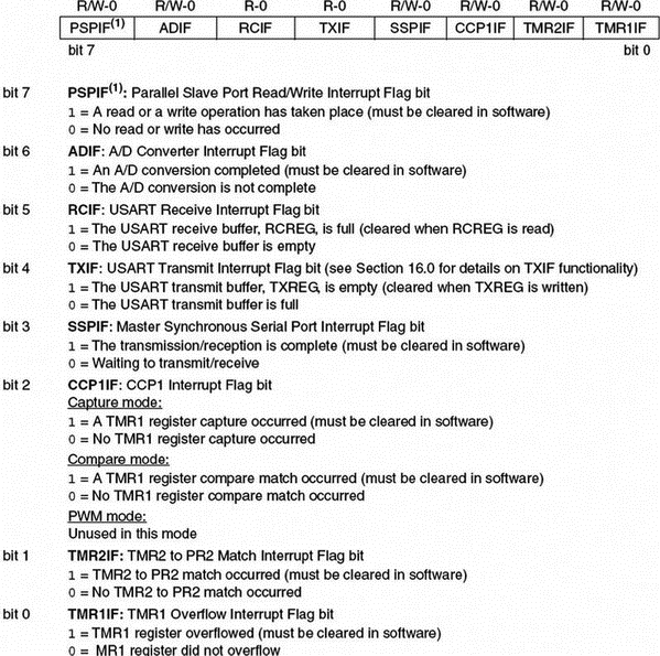
Figure 2.50: PIR1 bit definitions
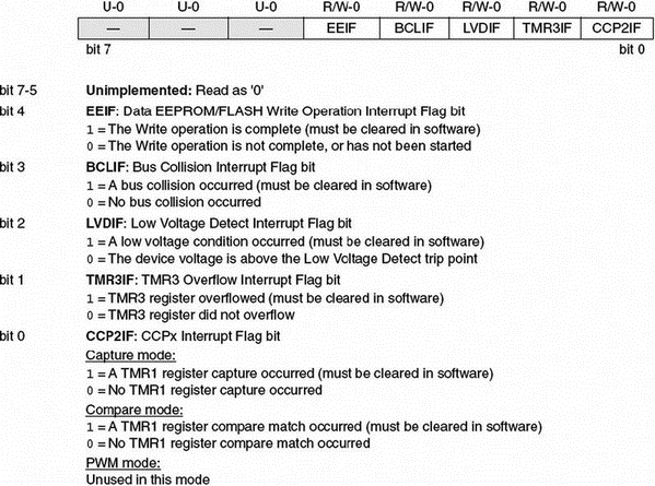
Figure 2.51: PIR2 bit definitions
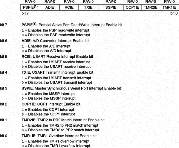
Figure 2.52: PIE1 bit definitions
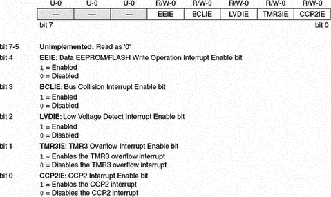
Figure 2.53: PIE2 bit definitions
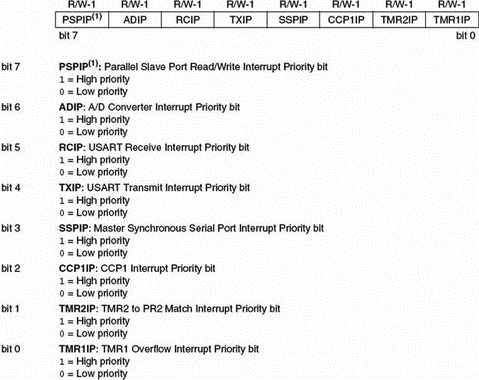
Figure 2.54: IPR1 bit definitions
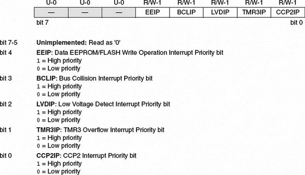
Figure 2.55: IPR2 bit definitions
Examples are given in this section to illustrate how the CPU can be programmed for an interrupt.
Example 2.2
Set up INT1 as a falling-edge triggered interrupt input having low priority.
Solution 2.2
The following bits should be set up before the INT1 falling-edge triggered interrupts can be accepted by the CPU in low-priority mode:
• Enable the priority structure. Set IPEN = 1
• Make INT1 an input pin. Set TRISB = 1
• Set INT1 interrupts for falling edge. SET INTEDG1 = 0
• Enable INT1 interrupts. Set INT1IE = 1
• Enable low priority. Set INT1IP = 0
• Clear INT1 flag. Set INT1IF = 0
• Enable low-priority interrupts. Set GIEL = 1
• Enable all interrupts. Set GIEH = 1
When an interrupt occurs, the CPU jumps to address 00008H in the program memory to execute the user program at the interrupt service routine.
Example 2.3
Set up INT1 as a rising-edge triggered interrupt input having high priority.
Solution 2.3
The following bits should be set up before the INT1 rising-edge triggered interrupts can be accepted by the CPU in high-priority mode:
• Enable the priority structure. Set IPEN = 1
• Make INT1 an input pin. Set TRISB = 1
• Set INT1 interrupts for rising edge. SET INTEDG1 = 1
• Enable INT1 interrupts. Set INT1IE = 1
• Enable high priority. Set INT1IP = 1
• Clear INT1 flag. Set INT1IF = 0
• Enable all interrupts. Set GIEH = 1
When an interrupt occurs, the CPU jumps to address 000018H of the program memory to execute the user program at the interrupt service routine.
- 2.1.1 Program Memory Organization
- 2.1.2 Data Memory Organization
- 2.1.3 The Configuration Registers
- 2.1.4 The Power Supply
- 2.1.5 The Reset
- 2.1.6 The Clock Sources
- 2.1.7 Watchdog Timer
- 2.1.8 Parallel I/O Ports
- 2.1.9 Timers
- 2.1.10 Capture/Compare/PWM Modules (CCP)
- 2.1.11 Analog-to-Digital Converter (A/D) Module
- 2.1.12 Interrupts
- 1.3.6 Interrupts
- 9.2.4. Traps, Exceptions, and Interrupts
- Chapter 10: Exceptions and Interrupts
- 10.2 What are Exceptions and Interrupts?
- 10.3 Applications of Exceptions and Interrupts
- 10.4 A Closer Look at Exceptions and Interrupts
- 10.4.1 Programmable Interrupt Controllers and External Interrupts
- 10.6 The Nature of Spurious Interrupts
- Interrupts
- 1.3.2 The Clock
- 1.3 Microcontroller Features
- 1.3.1 Supply Voltage
