Книга: Advanced PIC Microcontroller Projects in C
2.1.1 Program Memory Organization
2.1.1 Program Memory Organization
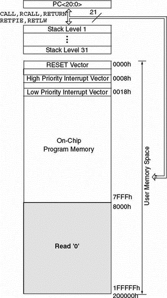
The program memory map is shown in Figure 2.3. All PIC18F devices have a 21-bit program counter and hence are capable of addressing 2Mbytes of memory space. User memory space on the PIC18F452 microcontroller is 00000H to 7FFFH. Accessing a nonexistent memory location (8000H to 1FFFFFH) will cause a read of all 0s. The reset vector, where the program starts after a reset, is at address 0000. Addresses 0008H and 0018H are reserved for the vectors of high-priority and low-priority interrupts respectively, and interrupt service routines must be written to start at one of these locations.

Figure 2.3: Program memory map of PIC18F452
The PIC18F microcontroller has a 31-entry stack that is used to hold the return addresses for subroutine calls and interrupt processing. The stack is not part of the program or the data memory space. The stack is controlled by a 5-bit stack pointer which is initialized to 00000 after a reset. During a subroutine call (or interrupt) the stack pointer is first incremented, and the memory location it points to is written with the contents of the program counter. During the return from a subroutine call (or interrupt), the memory location the stack pointer has pointed to is decremented. The projects in this book are based on using the C language. Since subroutine and interrupt call/return operations are handled automatically by the C language compiler, their operation is not described here in more detail.
Program memory is addressed in bytes, and instructions are stored as two bytes or four bytes in program memory. The least significant byte of an instruction word is always stored in an even address of the program memory.
An instruction cycle consists of four cycles: A fetch cycle begins with the program counter incrementing in Q1. In the execution cycle, the fetched instruction is latched into the instruction register in cycle Q1. This instruction is decoded and executed during cycles Q2, Q3, and Q4. A data memory location is read during the Q2 cycle and written during the Q4 cycle.
- 2.1.1 Program Memory Organization
- 2.1.2 Data Memory Organization
- 2.1.3 The Configuration Registers
- 2.1.4 The Power Supply
- 2.1.5 The Reset
- 2.1.6 The Clock Sources
- 2.1.7 Watchdog Timer
- 2.1.8 Parallel I/O Ports
- 2.1.9 Timers
- 2.1.10 Capture/Compare/PWM Modules (CCP)
- 2.1.11 Analog-to-Digital Converter (A/D) Module
- 2.1.12 Interrupts
- 2.1.2 Data Memory Organization
- Memory Analyzer (Formerly MemScope)
- Memory Overhead
- Detect Memory Leaks
- Memory maps
- EVENT MEMORY SIZE
- 2. How to Apply These Terms to Your New Programs
- The Programmers
- Для чего нужны папки Windows, Documents and Settings, Program Files и Temp?
- Можно ли указать использование по умолчанию вместо C:Program Files другого каталога для установки программ?
- Можно ли удалять из папки Program Files папки деинсталлированных программ?
- 6.1 Program Description Language (PDL)


