Êíèãà: Advanced PIC Microcontroller Projects in C
The Microcontroller Software
Ðàçäåëû íà ýòîé ñòðàíèöå:
The Microcontroller Software
The microcontroller receives the command P=nT from the PC and sends data byte n to PORTB. The listing of the microcontroller program (USB.C) without the USB code is shown in Figure 8.20. The program configures PORTB as digital output.
/*************************************************************************

                 USB BASED MICROCONTROLLER OUTPUT PORT

                =======================================

In this project a PIC18F4550 type microcontroller is connected to a PC through

the USB link.

A Visual Basic program runs on the PC where the user enters the bits to be set

or cleared on PORTB of the microcontroller. The PC sends a command to the

microcontroller requesting it to set or reset the required bits of the

microcontroller PORTB.

The command sent by the PC to the microcontroller is in the following format:

 P=nT

where n is the byte the microcontroller is requested to send to PORTB of the

microcontroller.

Author: Dogan Ibrahim

Date:   September 2007

File:   USB.C

*************************************************************************/

void main() {

 ADCON1 = 0xFF; // Set PORTB to digital I/O

 TRISB = 0;     // Set PORTB to outputs

 PORTB = 0;     // Clear all outputs

}

Figure 8.20: Microcontroller program without the USB code
Generating the USB Descriptor File
The USB descriptor file must be included at the beginning of the mikroC program. This descriptor file is created using the Tools menu option of the mikroC compiler as follows:
• Select Tools?HID Terminal
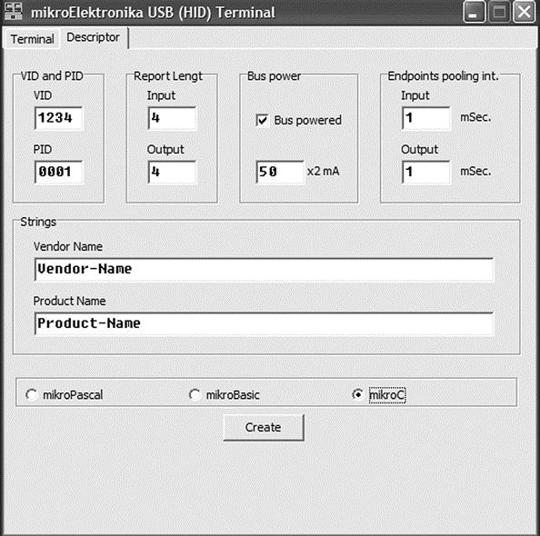
• A new form should be displayed. Click on the Descriptor tab and the form shown in Figure 8.21 is displayed.

Figure 8.21: Creating the USBdsc descriptor file
• The important parameters to enter here are vendor ID (VID), product ID (PID), input buffer size, output buffer size, vendor name (VN), and product name (PN). Note that the VID and PID are in hexadecimal format and that the values entered here must be the same as the ones used in the Visual Basic program when generating the code using the EasyHID wizard. Choose VID=1234 (equivalent to decimal 6460), PID=1, input buffer size=4, output buffer size=4, and any names you like for the VN and PN fields.
• Check the mikroC compiler.
• Clicking the CREATE button will ask for a folder name and then create descriptor file USBdsc in this folder. Rename this file to have extension “.C” (i.e., the full file name should be USBdsc.C) and then copy it to the following folder (other required mikroC files are already in this folder, so it makes sense to copy USBdsc.C here as well).
C:Program FilesMikroelektronikamikroCExamplesEasyPic4extra_examplesHID-libraryUSBdsc.c
Do not modify the contents of file USBdsc.C. A listing of this file is given on the CDROM.
The microcontroller program listing with the USB code included is shown in Figure 8.22 (program USB1.C). At the beginning of the program the USB descriptor file USBdsc.C is included. The operation of the USB link requires the microcontroller to keep the connection alive by sending keep-alive messages to the PC every several milliseconds. This is achieved by setting up a timer interrupt service routine using TIMER 0. Inside the timer interrupt service routine the mikroC USB function HID_InterruptProc is called. Timer TMR0L is reloaded and timer interrupts are re-enabled just before returning from the interrupt service routine.
/***************************************************************************

                  USB BASED MICROCONTROLLER OUTPUT PORT

                 =======================================

In this project a PIC18F4550 type microcontroller is connected

to a PC through the USB link.

A Visual Basic program runs on the PC where the user enters the bits to be

set or cleared on PORTB of the microcontroller. The PC sends a command to

the microcontroller requesting it to set or reset the required bits of the

microcontroller PORTB.

A 8MHz crystal is used to operate the microcontroller. The actual CPU clock

is raised to 48MHz by setting configuration bits. Also, the USB module is

operated with 48MHz.

The command sent by the PC to the microcontroller is in the following format:

 P=nT

where n is the byte the microcontroller is requested to send to PORTB of the

microcontroller.

This program includes the USB code.

Author: Dogan Ibrahim

Date:   September 2007

File:   USB1.C

****************************************************************************/

#include "C:Program FilesMikroelektronikamikroCExamplesEasyPic4extra_examplesHIDlibraryUSBdsc.c"

unsigned char Read_buffer[64];

unsigned char Write_buffer[64];

unsigned char num;

//

// Timer interrupt service routine

//

void interrupt() {

 HID_InterruptProc(); // Keep alive

 TMR0L = 100;         // Re-load TMR0L

 INTCON.TMR0IF = 0;   // Re-enable TMR0 interrupts

}

//

// Start of MAIN program

//

void main() {

 ADCON1 = 0xFF; // Set PORTB to digital I/O

 TRISB = 0;     // Set PORTB to outputs

 PORTB = 0;     // Clear all outputs

 //

 // Set interrupt registers to power-on defaults

 // Disable all interrupts

 //

 INTCON=0;

 INTCON2=0xF5;

 INTCON3=0xC0;

 RCON.IPEN=0;

 PIE1=0;

 PIE2=0;

 PIR1=0;

 PIR2=0;

 //

 // Configure TIMER 0 for 3.3ms interrupts. Set prescaler to 256

 // and load TMR0L to 100 so that the time interval for timer

 // interrupts at 48MHz is 256*(256-100)*0.083 = 3.3ms

 //

 // The timer is in 8-bit mode by default

 //

 T0CON = 0x47;      // Prescaler = 256

 TMR0L = 100;       // Timer count is 256-156 = 100

 INTCON.TMR0IE = 1; // Enable T0IE

 T0CON.TMR0ON = 1;  // Turn Timer 0 ON

 INTCON = 0xE0;     // Enable interrupts

 //

 // Enable USB port

 //

 Hid_Enable(&Read_buffer, &Write_buffer);

 Delay_ms(1000);

 Delay_ms(1000);

 //

 // Read from the USB port. Number of bytes read is in num

 //

 for(;;) // do forever

 {

  num=0;

  while(num != 4) // Get 4 characters

  {

   num = Hid_Read();

  }

  if (Read_buffer[0] == 'P' && Read_buffer[1] == '=' &&

   Read_buffer[3] == 'T') {

   PORTB = Read_buffer[2];

  }

 }

 Hid_Disable();

}

Figure 8.22: Microcontroller program with USB code
Inside the main program PORTB is defined as digital I/O and TRISB is cleared to 0 so all PORTB pins are outputs. All the interrupt registers are then set to their power-on-reset values for safety. The timer interrupts are then set up. The timer is operated in 8-bit mode with a prescaler of 256. Although the crystal clock frequency is 8MHZ, the CPU is operated with a 48MHz clock, as described later. Selecting a timer value of TMR0L . 100 with a 48MHz clock (CPU clock period of 0.083?s) gives timer interrupt intervals of:
(256 – 100) * 256 * 0.083?s
or, about 3.3ms. Thus, the keep-alive messages are sent every 3.3ms.
The USB port is then enabled by calling function Hid_Enable. The program then enters an indefinite loop and reads data from the USB port with Hid_Read. When 4 bytes are received at the correct format (i.e., byte 0=“P,” byte 1=“.”, and byte 3=“T”) then the data byte is read from byte 2 and sent to PORTB of the microcontroller.
It is important to note that when data is received using the Hid_Read function, the function returns the number of bytes received. In addition, the first byte received is the first actual data byte and not the report ID.
Microcontroller Clock
The USB module of the PIC18F4550 microcontroller requires a 48MHz clock. In addition, the microcontroller CPU requires a clock that can range from 0 to 48MHz. In this project the CPU clock is set to be 48MHz.
There are several ways to provide the required clock pulses.
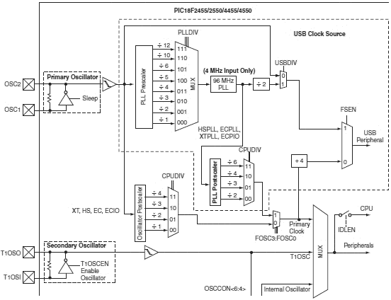
Figure 8.23 shows part of the PIC18F4550 clock circuit. The circuit consists of a 1:1–1:12 PLL prescaler and multiplexer, a 4:96MHz PLL, a 1:2–1:6 PLL postscaler, and a 1:1–1:4 oscillator postscaler. Assuming the crystal frequency is 8MHz and we want to operate the microcontroller with a 48MHz clock, and also remembering that a 48MHz clock is required for the USB module, we should make the following choices in the Edit Project option of the mikroC IDE:
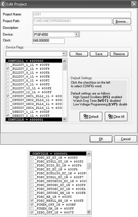
• Set _PLL_DIV2_1L so the 8MHz clock is divided by 2 to produce 4MHZ at the output of the PLL prescaler multiplexer. The output of the 4:96MHZ PLL is now 96MHz. This is further divided by 2 to give 48MHz at the input of multiplexer USBDIV.
• Check _USBDIV_2_1L to provide a 48MHz clock to USB module and to select ?2 for the PLL postscaler.
• Check CPUDIV_OSC1_PLL2_1L to select PLL as the clock source.
• Check _FOSC_HSPLL_HS_1H to select a 48MHz clock for the CPU.
• Set the CPU clock to 48MHz in mikroC IDE (using Edit Project).

Figure 8.23: PIC18F4550 microcontroller clock
The clock bits selected for the 48MHz USB operation with a 48MHz CPU clock are shown in Figure 8.24.

Figure 8.24: Selecting clock bits for USB operation
Setting other configuration bits in addition to the clock bits is recommended.
The following list gives all the bits that should be set in the Edit Project option of the IDE (most of these settings are the power-on-reset values of the bits):
PLLDIV_2_1L

CPUDIV_OSC1_PLL2_1L

USBDIV_2_1L

FOSC_HSPLL_HS_1H

FCMEM_OFF_1H

IESO_OFF_1H

PWRT_ON_2L

BOR_ON_2L

BORV_43_2L

VREGEN_ON_2L

WDT_OFF_2H

WDTPS_256_2H

MCLRE_ON_3H

LPT1OSC_OFF_3H

PBADEN_OFF_3H

CCP2MX_ON_3H

STVREN_ON_4L

LVP_OFF_4L

ICPRT_OFF_4L

XINST_OFF_4L

DEBUG_OFF_4L
- 1.4 Microcontroller Architectures
- 4.3.3 Software UART Library
- 5.1 Software Development Tools
- Further Development
- Testing the Program
- The PC Software
- Testing the Project
- Using the HID Terminal of mikroC
- 4.4.4 The Dispatcher
- Introduction to Microprocessors and Microcontrollers
- About the author
- Chapter 7. The state machine


