Êíèãà: Advanced PIC Microcontroller Projects in C
PROJECT 8.3 — USB-Based Ambient Pressure Display on the PC
PROJECT 8.3 — USB-Based Ambient Pressure Display on the PC
In this project, an ambient atmospheric pressure sensor is connected to a PIC18F4550 microcontroller, and the measured pressure is sent and displayed on a PC every second using a USB link.
An MPX4115A-type pressure sensor is used in this project. This sensor generates an analog voltage proportional to the ambient pressure. The device is available in either a 6-pin or an 8-pin package.
The pin configuration of a 6-pin sensor is:
Pin Description

1   Output voltage

2   Ground

3   +5V supply

4–6 not used
and for an 8-pin sensor:
Pin Description

1   not used

2   +5V supply

3   Ground

4   Output voltage

5–8 not used
Figure 8.34 shows pictures of this sensor with both types of pin configurations.
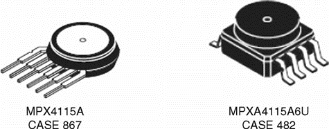
Figure 8.34: MPX4115A pressure sensors
The output voltage of the sensor is determined by:
V = 5.0 * (0.009 * kPa – 0.095) (8.1)
or

where
kPa = atmospheric pressure (kilopascals)
V = output voltage of the sensor (V)
The atmospheric pressure measurements are usually shown in millibars. At sea level and at 15°C the atmospheric pressure is 1013.3 millibars. In Equation (8.2) the pressure is given in kPa. To convert kPa to millibars we have to multiply Equation (8.2) by 10 to give:

or

Figure 8.35 shows the variation of the output voltage of MPX4115A sensor as the pressure varies. We are interested in the range of pressure between 800 and 1100 millibars.
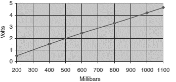
Figure 8.35: Variation of sensor output voltage with pressure
The steps to calculate the pressure in millibars are:
• Read the output voltage of the pressure sensor using one of the A/D channels of the microcontroller
• Use Equation (8.4) to convert the voltage into pressure in millibars
The block diagram of the project is shown in Figure 8.36.
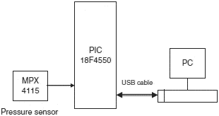
Figure 8.36: Block diagram of the project
The circuit diagram of the project is shown in Figure 8.37. The sensor output is connected to analog input AN0 of the microcontroller. As in Project 8.2, the USB connector is connected to port pins RC4 and RC5 and the microcontroller is operated from an 8MHz crystal.
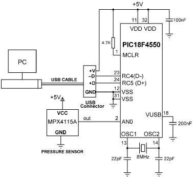
Figure 8.37: Circuit diagram of the project
The program on the PC is based on Visual Basic, as in the previous projects. A single form is used, as shown in Figure 8.38, to display the pressure in millibars every second.
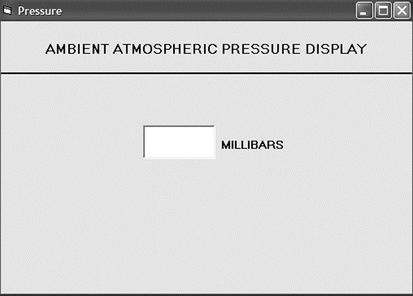
Figure 8.38: Visual Basic form to display pressure
The microcontroller program listing (named PRESSURE.C) of the project is given in Figure 8.39. At the beginning of the main program the PORTA pins are defined as analog inputs by clearing ADCON1 to 0 and setting port pins as inputs. Then the interrupt registers are set to their default power-on values. Timer interrupt TMR0 is set to generate an interrupt every 3.3ms to keep the USB bus alive. The USB port of the microcontroller is then enabled, and ADCON2 is initialized by setting the A/D clock frequency to Fosc/64.
/***************************************************************************

             USB BASED ATMOSPHERIC PRESSURE DISPLAY ON PC

             ============================================

In this project a PIC18F4550 type microcontroller is connected

to a PC through the USB link.

In addition, a MPX4115A type pressure sensor IC is connected to analog port

AN0 of the microcontroller. The microcontroller reads the atmospheric

pressure and sends it to the PC every second. The PC displays the pressure

on the screen.

A Visual Basic program runs on the PC which reads the pressure from the USB

port and then displays it on a form.

The microcontroller is operated from a 8MHz crystal, but the CPU clock

frequency is increased to 48MHz. Also, the USB module operates with 48MHz.

The pressure is sent to the PC in millibars as a 4 digit integer number.

Author: Dogan Ibrahim

Date:   September 2007

File:   PRESSURE.C

****************************************************************************/

#include "C:Program FilesMikroelektronikamikroCExamplesEasyPic4extra_examplesHIDlibraryUSBdsc.c"

unsigned char num,i,j;

unsigned long Vin, Pint;

unsigned char op[12], Pressure[4], Read_buffer[4];

float mV,V,Pmb;

//

// Timer interrupt service routine

//

void interrupt() {

 HID_InterruptProc(); // Keep alive

 TMR0L = 100;         // Reload TMR0L

 INTCON.TMR0IF = 0;   // Re-enable TMR0 interrupts

}

//

// Start of MAIN program

//

void main() {

 ADCON1 = 0;   // Set inputs as analog, Ref=+5V

 TRISA = 0xFF; // Set PORT A as inputs

 //

 // Set interrupt registers to power-on defaults

 // Disable all interrupts

 //

 INTCON=0;

 INTCON2=0xF5;

 INTCON3=0xC0;

 RCON.IPEN=0;

 PIE1=0;

 PIE2=0;

 PIR1=0;

 PIR2=0;

 //

 // Configure TIMER 0 for 3.3ms interrupts. Set prescaler to 256

 // and load TMR0L to 156 so that the time interval for timer

 // interrupts at 48MHz is 256*156*0.083 = 3.3ms

 //

 // The timer is in 8-bit mode by default

 //

 T0CON = 0x47;      // Prescaler = 256

 TMR0L = 100;       // Timer count is 256-156 = 100

 INTCON.TMR0IE = 1; // Enable T0IE

 T0CON.TMR0ON = 1;  // Turn Timer 0 ON

 INTCON = 0xE0;     // Enable interrupts

 //

 // Enable USB port

 //

 Hid_Enable(&Read_buffer, &Pressure);

 Delay_ms(1000);

 Delay_ms(1000);

 //

 // Configure A/D converter. AN0 is used in this project

 //

 ADCON2 = 0xA6; // A/D clock = Fosc/64, 8TAD

 //

 // Endless loop. Read pressure from the A/D converter,

 // convert into millibars and send to the PC over the

 // USB port every second

 //

 for(;;) // do forever

 {

  Vin = Adc_Read(0);            // Read from channel 0 (AN0)

  mV = (Vin * 5000.0) / 1024.0; // In mv=Vin x 5000/1024

  V = mV / 1000.0;              // Pressure in Volts

  Pmb = (2.0*V + 0.95) / 0.009; // Pressure in mb

  Pint = (int)Pmb;              // As an integer number

  LongToStr(Pint,op);           // Convert to string in "op"

  //

  // Remove leading blanks

  //

  for(j=0; j<4; j++) Pressure[j]=' ';

  j=0;

  for(i=0;i<=11;i++) {

   if(op[i] != ' ') // If a blank

   {

    Pressure[j]=op[i];

    j++;

   }

  }

  //

  // Send pressure (in array Pressure) to the PC

  //

  Hid_Write(&Pressure,4); // Send to USB as 4 characters

  Delay_ms(1000);         // Wait 1 second

 }

 Hid_Disable();

}

Figure 8.39: Microcontroller program of the project
An endless loop is formed using a for statement. Inside this loop the pressure sensor data is read into variable Vin and then converted into physical voltage in millivolts and stored in variable mV. The atmospheric pressure is then calculated using Equation (8.4) and stored in variable Pint as a long integer. The mikroC function LongToStr converts this integer into a string in array op. Any leading spaces are removed from this array, and the resulting pressure is stored in a character array called Pressure. The mikroC USB function Hid_Write is then called to send the pressure data to the USB bus as 4-character data. The program then waits for one second, and the above process is repeated forever.
An 8MHz crystal is used to provide clock pulses to the microcontroller. The microcontroller CPU clock and the USB module are operated at 48MHz, and the clock and configuration register settings are as in the other projects in this chapter.
The PC program, based on Visual Basic, is called PRESSURE. Subroutine OnRead receives the data arriving at the USB port of the PC and then displays it on the screen form. The program does not send any data to the USB bus. The program listing (except the global variable declarations) is given in Figure 8.40.
' vendor and product IDs

Private Const VendorID = 4660

Private Const ProductID = 1

' read and write buffers

Private Const BufferInSize = 8

Private Const BufferOutSize = 8

Dim BufferIn(0 To BufferInSize) As Byte

Dim BufferOut(0 To BufferOutSize) As Byte

Private Sub Command1_Click()

 Form_Unload (0)

 End

End Sub

'*******************************************************************

' when the form loads, connect to the HID controller - pass

' the form window handle so that you can receive notification

' events...

'*******************************************************************

Private Sub Form_Load()

 ' do not remove!

 ConnectToHID (Me.hwnd)

 lblstatus = "Connected to HID..."

End Sub

'********************************************************************

' disconnect from the HID controller...

'********************************************************************

Private Sub Form_Unload(Cancel As Integer)

 DisconnectFromHID

End Sub

'********************************************************************

' a HID device has been plugged in...

'********************************************************************

Public Sub OnPlugged(ByVal pHandle As Long)

 If hidGetVendorID(pHandle) = VendorID And hidGetProductID(pHandle) = _

  ProductID Then

  lblstatus = "USB Plugged....."

 End If

End Sub

'********************************************************************

' a HID device has been unplugged...

'********************************************************************

Public Sub OnUnplugged(ByVal pHandle As Long)

 If hidGetVendorID(pHandle) = VendorID And hidGetProductID(pHandle) = _

  ProductID Then

  lblstatus = "USB Unplugged...."

 End If

End Sub

'********************************************************************

' controller changed notification - called

' after ALL HID devices are plugged or unplugged

'********************************************************************

Public Sub OnChanged()

 Dim DeviceHandle As Long

 ' get the handle of the device we are interested in, then set

 ' its read notify flag to true - this ensures you get a read

 ' notification message when there is some data to read...

 DeviceHandle = hidGetHandle(VendorID, ProductID)

 hidSetReadNotify DeviceHandle, True

End Sub

'********************************************************************

' on read event...

'********************************************************************

Public Sub OnRead(ByVal pHandle As Long)

 Dim pressure As String

 If hidRead(pHandle, BufferIn(0)) Then

  ' The first byte is the report ID. i.e. BufferIn(0)=reportID

  pressure = Chr(BufferIn(1)) & Chr(BufferIn(2)) & Chr(BufferIn(3)) & _

   Chr(BufferIn(4))

  txtno = pressure

 End If

End Sub

Figure 8.40: Visual Basic program of the project
Figure 8.41 shows a typical output from the Visual Basic program, displaying the atmospheric pressure.
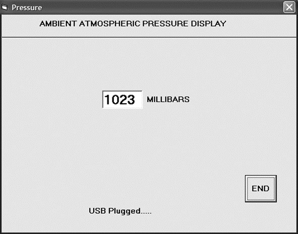
Figure 8.41: Typical output from the Visual Basic program
An installable version of the Visual Basic program is provided on the CDROM that comes with this book, in folder PRESSURE.
- 8.1 Speed Identification on the Bus
- 8.2 USB States
- 8.3 USB Bus Communication
- 8.4 Descriptors
- 8.5 PIC18 Microcontroller USB Bus Interface
- 8.6 mikroC Language USB Bus Library Functions
- PROJECT 8.1 — USB-Based Microcontroller Output Port
- PROJECT 8.2 — USB-Based Microcontroller Input/Output
- PROJECT 8.3 — USB-Based Ambient Pressure Display on the PC
- 8.1 Speed Identification on the Bus
- The Project
- 4.4.4 The Dispatcher
- About the author
- Chapter 7. The state machine
- Chapter 16. Commercial products based on Linux, iptables and netfilter
- Appendix E. Other resources and links
- Project PDL
- Example NAT machine in theory
- The final stage of our NAT machine
- Compiling the user-land applications
- The conntrack entries
