Книга: Introduction to Microprocessors and Microcontrollers
Serial transmission
Serial transmission
To send information in serial form requires only a simple communication link but it is inevitably slower than parallel transmission since the data is only sent one bit at a time.
UARTs
To convert the parallel data on the data bus of the microprocessor to a serial transmission we could use a shift register as in Chapter 6. The modern alternative is to use a chip called a UART (universal asynchronous receiver/transmitter) or USART (universal synchronous/asynchronous receiver/transmitter).
These are integrated circuits that convert data from parallel to serial transmission so instead of having eight wires, each carrying a single bit at the same time, the serial transmission passes the bits, one at a time along a single wire. It can also receive eight bits of serial data then pass it into the microprocessor in a single byte. Parallel transmission is obviously a lot faster since eight bits are moved at a time but it requires eight connections. To send a fax signal, for example, would require the use of eight telephone lines whereas the UART can convert it to a serial transmission and sent it over a single line at one-eighth of the speed.
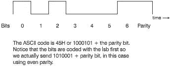
UARTS do a lot more than a shift register. They include parity checking and buffers to enable it to handle about 16 bytes at a time without involving the microprocessor. Most transmissions involve the ASCII code to represent the characters to be transmitted. This is a seven-bit code to represent each alphanumeric character and a variety of control instructions. For example, the letter E is 45 in hex which, using only the lower seven bits, is 1000101. The ASCII code is used in both parallel and serial transmissions. Each letter and symbol has its own seven-digit code. A further bit is added on the end to provide a parity bit or it can be used to swap over to an alternative set of characters to allow mathematical symbols and Greek letters to be transmitted or, if unused, can be left at zero. Our letter E would then be represented as shown in Figure 17.8.

Figure 17.8 Coding in ASCII
When using ASCII signals in a serial transmission, we need to be able to tell the receiving apparatus when a particular ASCII character has been sent. This is easily done in a synchronous system that ensures that the transmitter and the receiver are locked together running at the same speed. This is not the easiest way of operating the system owing to the difficulties of ensuring the two devices remain synchronous. Therefore, we tend to operate asynchronously. This means that we have to send a signal along with each ASCII code to tell the receiver when the code has started and when it has stopped. Otherwise the transmitter would send a continuous stream of data and if a bit were lost, the receiver would get out of step and would misread all subsequent data.
To get round this problem, a 0 V ‘start’ bit is sent at the beginning of the character and a positive ‘stop’ bit is sent at the end. This brings a seven-bit ASCII code up to a total of 10 bits. The start and stop bits ensure that there is at least one change of level for each character that can be used to keep the receiver clock nearly synchronized to the transmitter for the time taken to receive that character.
For distances over a few metres, we need to use a slightly more sophisticated transmission system to prevent random noise from interfering too much. There are several systems in use, the most popular being those created by the EIA (Electrical Industries Association).
As with most transmission media, there is a trade off between the speed and the maximum distance the system can be used for. If you intend pushing the transmission distance to its maximum value, you will have to accept a reduced speed. As a rule of thumb, halve the speed if you double the distance.
RS232C
This is one of the transmission standards created by the EIA committee. This standard allows for transmissions up to 50 feet (15 m) and at speeds of up to 20 kbaud (it can actually exceed this speed and distance but it’s not guaranteed). The baud is the measure of the speed of transmission. It is the number of clock periods per second, which approximates to the number of bits per second. The RS232C transmission is balanced at about 0 V. Here’s the time to be careful, the binary one level is a negative voltage (between –5 and –15 V) and a binary zero level is a positive value between +5 and +15 V. This seems upside down compared with all our previous uses of binary. Our letter E would be transmitted as in Figure 17.9. The transmitter levels are specified as ±5 V but the receiver limits are ±3 V. This allows for a noise spike to be up to 6 V before there is any possibility of misreading a piece of data.

Figure 17.9 RS232C transmission
RS423A
This is an improved version having a maximum speed of 100 kbits/s and a maximum cable length of ? mile (1.2 km). The transmission voltages have to be between ±3.6 and 6 V and the receiver can go down to ±0.2 V.
Changing voltage levels
How do we change the binary or logic values into the RS232 voltage levels? If you are building a microprocessor-based system then the most obvious way is to use a pair of integrated circuits called the 1488 (transmitter) and the 1489 (receiver). These integrated circuits have been around for many years and are simple and reliable. They have a small snag in that they need 12 V supplies whereas nowadays 5 V supplies are much more common so you may find some new transceivers (made by Maxim) more interesting. These only require a single +5 V supply and generate their own ± voltages for the RS232C transmission. Each chip contains two transmitters and two receivers and operate up to 120 kbits/s. The devices are numbered MAX202, MAX208, MAX220 and MAX232 and others. PCs have a serial port that provides signals at RS232C levels.
Using RS232C in real life
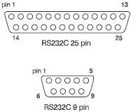
Most RS232C links are via a 25-pin ‘D’ plug or a 9-pin ‘D’ plug and socket (Figure 17.10) but unlike the Centronics which is quite stable and usually work straight off, the RS232C can be a real nuisance. Before attempting to communicate, you must ensure that the transmitter and the receiver are using the same word length and parity values are set for the same speed of operation. Even then, it may take some experimenting before they spring into life. The problem is that there are many more options for the other connections. All have to be agreed between the receiver and the transmitter. The specifications are not detailed enough and can lead to different interpretations. It is not surprising that it is often insufficient to connect an RS232C cable between two pieces of equipment and switch on. You will need to get hold of the RS232C connection specification and settle down in a comfortable chair.

Figure 17.10 ‘D’ connectors for RS232C
Modems
A modem (MOdulator DEModulator) converts a digital signal into two audio tones so that the transmission can occur along a telephone line. Telephones are generally designed to accept frequencies between 300 Hz and 3.1 kHz. This relatively narrow bandwidth was chosen to allow speech to be transferred with undue loss of quality while allowing the largest number of calls to be passed along the same cable. Once the digital signals are on a telephone line then the range is unlimited.
- Serial and parallel transmission
- Data transmission
- Binary Serialization
- Introduction to Serial Devices
- Maintaining Accurate Serial Numbers
- Chapter 4. Configuring the Serial Hardware
- 14.3.1. gdb Remote Serial Protocol
- 14.5.1. Early Serial Debug Output
- 15.5.1. Debugging via Serial Port
- 1.3.9 Serial Input-Output
- PROJECT 6.10 — Serial Communication–Based Calculator
- Using Software-Based Serial Communication


