Книга: Introduction to Microprocessors and Microcontrollers
Serial and parallel transmission
Serial and parallel transmission
In sending information in digital form, we have a choice of using serial or parallel transmission. In the case of serial transmission, the binary values are represented by two different voltage levels and are sent one after the other along a cable. This is simple but slow. The alternative is to have several wires and thus be able to send several bits of data at the same time, one on each conductor.
In a microprocessor-based system, even if it is a one-off, it is usually better to conform to established standards for the cabling so that other instruments and circuits can be connected with a minimum of hassle.
Parallel connection
There are several different standards used for parallel connection of data but one of the most widely used, and most reliable, was produced by Centronics.
The Centronics system sends eight bits at a time and employs a 36 plug and socket system. To send data, there are four basic control signals as well as the eight data lines. It also stipulates a variety of other control wires that can be used if required.
The important thing to remember about these standards is that you do not have to use all the connections listed but those that you do decide to use should conform to the stated specification and be on the correct pins. This ensures that if the plug is inserted into a new piece of equipment, it may not work but at least it will not be damaged.
Centronics data transmission
To see how the system works, we will use timing diagrams to show what happens and when. These diagrams, which all look very similar at first glance, are shown in all data manuals to show the sequence of events inside the microprocessor and in the surrounding circuit.
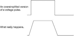
There are a couple of points that are worth mentioning. We have mentioned the problem of rise time in Chapter 7. You will remember that we cannot change a voltage level instantaneously. It may not seem an important delay when we think of switching a light on at home but when the microprocessor is handling data at millions of bits per second, these delays can be important and is a common cause of failure in a circuit that ‘should’ work. Most waveform diagrams show the ends of a square wave as sloping lines rather than vertical ones.
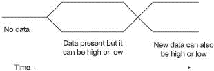
In Figure 17.5 we have a positive-going pulse to represent a data value of 1 but, of course, data could equally well be at 0 V to represent a binary 0. In cases where we want to show that a level has changed, but it may go to either level, we redraw the diagram to show both possibilities at the same time, as in Figure 17.6.

Figure 17.5 Rise and fall time may be important

Figure 17.6 Showing alternative data levels
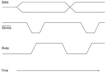
Figure 17.7 shows the process of transferring eight bits of data from a microprocessor to an external printer or other device.

Figure 17.7 The timing of Centronics signals
Step 1 The microprocessor puts the eight bits of data on the data wires.
Step 2 A short delay occurs while we wait for the data voltages to settle on all the eight wires. Then the strobe pulse occurs to tell the printer or other accessory that the data is ready. The line over the word strobe indicates that it is active low. No line would mean active high.
Step 3 The printer starts loading data and the busy line goes high to prevent more data being sent.
Step 4 When the data has been printed, the busy line goes down to tell the microprocessor to put the next piece of data onto the data wires.
The standard allows for many other control wires for other purposes. In this example, the eight data wires have been used as outputs from the microprocessor but it is quite possible to use them to carry input data although this is not allowed for in the design of PCs.
- Разработка приложений баз данных InterBase на Borland Delphi
- Open Source Insight and Discussion
- Introduction to Microprocessors and Microcontrollers
- Chapter 6. Traversing of tables and chains
- Chapter 8. Saving and restoring large rule-sets
- Chapter 11. Iptables targets and jumps
- Chapter 5 Installing and Configuring VirtualCenter 2.0
- Chapter 16. Commercial products based on Linux, iptables and netfilter
- Appendix A. Detailed explanations of special commands
- Appendix B. Common problems and questions
- Appendix E. Other resources and links
- IP filtering terms and expressions


