Книга: Introduction to Microprocessors and Microcontrollers
Analog to digital conversion (A to D or ADC or A–D)
Analog to digital conversion (A to D or ADC or A–D)
Inevitably these days, this is taken care of by an integrated circuit of which there are many different designs. It is quite possible, but totally uneconomic, to construct our own ADC so it is really a matter of flicking through the catalogues and choose the most appropriate one available.
There are several different designs of ADCs, which are based on three basically different approaches.
Flash converter
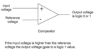
The first is called a flash converter or parallel encoder. These use circuits called comparators. A comparator has two inputs, one is the analogue voltage being converted and the other is a known reference voltage.
All we ask of a comparator is to answer a simple question: ‘Is the analogue input voltage higher or lower than our reference voltage?’ It answers by changing its output voltage to a logic 1 to mean it is higher and a logic 0 to mean it is lower. They are so accurate that the chance of it accepting the two voltages as the same level are extremely slight and doesn’t happen in practice (see Figure 17.2).

Figure 17.2 A comparator used in a flash ADC
So how do we use the comparator? If we had three of them with reference voltages set to 1 V, 2 V and 3 V and then applied the input voltage of 2.5 V to all of them, the first two would set their outputs to a level 1 and the last one would be unaffected at logic 0. The logic levels could be used to generate a binary number to represent 2.5 V.
An input voltage of 2.4 V or 2.9 V would also result in the same comparators being activated and hence the same output digital signal. This error occurs in all analog to digital converters. We can reduce the size of the error by increasing the number of comparators to detail more levels. Real ones have between 16 and 1024 different levels.
Ramp generators
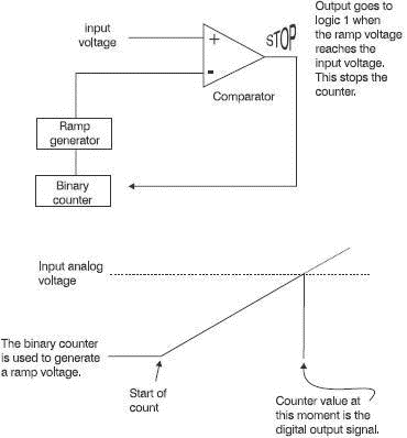
These are a combination of a binary counter that simply counts up from zero to its maximum value, perhaps 1024 like the last type. As the binary count proceeds, a ramp voltage is made to steadily increase. A single comparator is used to compare the output of the ramp voltage with the analog voltage being converted. As soon as the ramp voltage exceeds the input voltage, the comparator signal stops the counter. The counter output is then the digital equivalent of the analog signal (see Figure 17.3).

Figure 17.3 An ADC that uses a ramp voltage
Successive approximation
If we were to use a 3-bit digital signal to convert an analog voltage of between 0 V and 4 V we could have the 3 bits representing voltages of 4 V, 2 V and 1 V. This is how the circuit responds to an input of 3.5 V.
The digits are initially set to 000. The left-hand bit is switched on and its 4 V is compared with the input. The input is seen to be less than this so this digit is reset to zero. It then tries the next bit and its 2 V are compared and found to be less than the input so it remains set. The digital signal is now 010. The circuit now adds the 1 V from the last digit. The result is a total of 3 V, which is compared with the input analog signal. The input of 3.5 V still exceeds the current value of 3 V so the last bit is set. The final digital output is 011.
The circuit has tried all the available values until it finds the one that provides the result closest, but less than the input signal. As before, the more bits we are using, the more accurate is the result.
In checking the specifications of likely ADCs to use, we need to compare the following criteria.
Quantization error
In the above example using the flash converter, we can see that an analog input of 3.5 V would provide the same output as would any value between slightly over 3 V and slightly less than 4 V. This error means that small variation in the analog input voltage will be lost. The size of this error is equal to the space between the comparator reference voltages.
Changing from eight comparators to 1024, would mean that the voltage gaps would decrease from 1 V to 7.8 mV as would the quantization error. Regardless of the method used for A–D conversion, quantization error is always present.
Bits
The more bits, the merrier. Likely values will be between 8 and 16.
Speed
There are two factors here. How often can we get an updated value for the signal and how well can we follow any changes it is making? Even if we do not want the signal to be sampled at a very high rate, we still may want to take a quick sample so that the input value is unlikely to change very much as the sample is actually being measured.
For speed, you cannot beat the flash converter. It can sample for a period as short as 3 ns which compares very favourably with the typical values of 10 ?s for the ramp generators and successive approximation types.
- Type Conversion
- Using Digital Cameras with Fedora
- Handheld Digital Cameras
- Configuring FTP Server File-Conversion Actions
- An Example of Conversions in Action
- 3.2.5. Broadcom MIPS
- 1.3.8 Analog-to-Digital Converter
- 1.3.12 Analog Comparator
- 2.1.11 Analog-to-Digital Converter (A
- 7.7.4 Broadcast Communication
- Использование Analog
- Digital UNIX


