Книга: Introduction to Microprocessors and Microcontrollers
Interrupts
Interrupts
Interrupts were introduced in Chapter 8 when we looked at the operation of the interrupt flag in the status or flag register but we will now delve a little further into the system.
All microprocessors have interrupts that can be initiated either by the software being run at the time or by external hardware circuits. Microprocessors differ in the details of their response to hardware interrupts and in the number of different interrupt pins offered. Details are always itemized in the technical data supplied with the device.
The likely options are as follows
There are two basic types of hardware interrupt. The first is an interrupt request or IRQ (or INTR) pin. This tells the microprocessor that it would like to have some attention. Since it is a request rather than an order, the microprocessor is free to say ‘yes’ or ‘no’ or ‘yes, but not at the moment – just wait till I’m ready’. This does not imply any intelligence on the part of the microprocessor – it must be told which response to give by the software that is being run at the time. In the absence of any instruction, it normally accepts the interruption. If a particular interrupt pin has been told not to respond to an interrupt, we say that the interrupt has been ‘masked’.
The second type is called a non-maskable interrupt, that is, an unstoppable demand for attention. This will always assume top-priority. A typical use for this would be for an emergency shutdown in the event of a power failure. The program can also instigate an interrupt by means of a software instruction as part of a program.
What is a hardware interrupt signal?
This is a change of voltage on an interrupt pin generated by the external device. The change required would be detailed in the technical data but there are four choices.
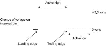
The first two choices are changes of voltage level. The pin can sit at +3.3 V or whatever the ‘high’ voltage happens to be, then responds when it falls to 0 V. We call this ‘active low’. When the pin goes low, an interrupt is recognized. Alternatively, it could sit at 0 V and become activated by an increased voltage. This we call ‘active high’.
The alternative approach is to use the sudden change of level. From low to high is called ‘leading edge’ or ‘rising edge’ and from high to low is the ‘trailing edge’ or ‘falling edge’ (See Figure 17.1 and have a glance at Figure 6.4 to see the alternative names.)

Figure 17.1 Four ways of signalling an interrupt
Once an interrupt is activated, the signal must be returned to its normal voltage before it can be triggered again. The input is masked as the interrupt program is running to prevent the interrupt pin from interrupting itself if the voltage remains at its active level.
Accommodating several external devices
The simplest and quickest way of connecting devices to the interrupts of a microprocessor is to have each device connected to its own interrupt pin. This is OK providing there are enough pins. Few microprocessors have more than two interrupt pins so we have to connect several devices to the same pin.
When an interrupt occurs, a program called the ‘first level interrupt handler’ or FLIH is activated. The function of the FLIH is to identify the device causing the interrupt and to pass the controls over to the ‘interrupt handler’ or ‘interrupt service routine’ program that has been written to deal with that device.
How does it know which device is crying for help? There are two options, polling and vectored interrupts.
Polling interrupts
This is a slow but sure way. Each possible device is interrogated in turn with an ‘is it you?’ signal until the source of the interrupt is found. The order of checking is prioritized so the most important device is checked first.
Vectored interrupts
Immediately after the interruption has occurred, the FLIH puts out a ‘who’s there?’ signal and the interrupting circuit puts an identification signal onto the data bus. This signal is usually used as part of an address to identify the section of program to be executed.
What happens if an interrupt is received while the previous interrupt is being dealt with? Again we have a choice. We can disable the new interrupt until the first one is complete, then deal with the new one. Alternatively, we can check the priority of the new alarm and decide on the new priorities. A higher priority causes the present interrupt to be halted and its current state to be saved in the stack while the new one is worked on and then we return to unload the stack information and carry on with the original problem. If the new interrupt is less important it gets a ‘wait a bit’ message until the first one is finished.
In a microprocessor-based system it is up to the designer to decide on the priorities and uses of the interrupts. In a PC, the interrupts are prioritized in order of speed and importance. Top priority is given to the internal clock. This is the clock that tells us the time – not the square wave clock that synchronizes the circuitry. Thereafter, in order, we have the keyboard, two spare ones for any other operations, then comes the serial port, the hard drive, the floppy disk drive and finally the printer.
- 1.3.6 Interrupts
- 2.1.12 Interrupts
- 9.2.4. Traps, Exceptions, and Interrupts
- Chapter 10: Exceptions and Interrupts
- 10.2 What are Exceptions and Interrupts?
- 10.3 Applications of Exceptions and Interrupts
- 10.4 A Closer Look at Exceptions and Interrupts
- 10.4.1 Programmable Interrupt Controllers and External Interrupts
- 10.6 The Nature of Spurious Interrupts
- 1.3.2 The Clock
- 1.3 Microcontroller Features
- 1.3.1 Supply Voltage


