Книга: Advanced PIC Microcontroller Projects in C
5.3.5 Using a Development Board
5.3.5 Using a Development Board
It is easy to develop microcontroller-based applications with the help of a development board. This section explains how to use the development board BIGPIC4, described earlier in this chapter. The program written in Example 5.1 is compiled and then loaded to the microcontroller using the on-board mikroICD in-circuit emulator. Then the program runs and displays the sum of the numbers 1 to 10 on the LEDs connected to PORTC.
However, before using the development board we need to know how the BIGPIC4 is organized and how to use the various devices on the board.
BIGPIC4 Development Board
Figure 5.57 shows the BIGPIC4 development board with the functions of various devices identified with arrows. The board can be powered either from an external power supply (8-to 16-C AC/DC) or from the USB port of a computer, using a jumper. In this application, the board is powered from a USB port.
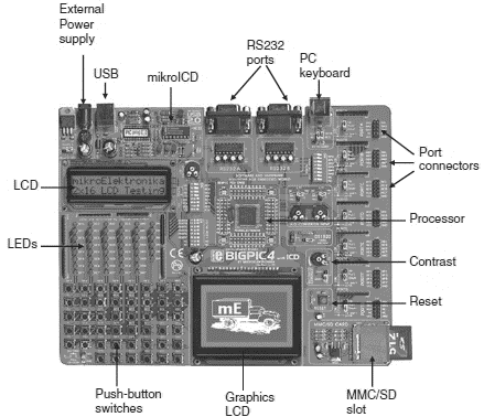
Figure 5.57: BIGPIC4 development board
A 2-row by 16-column LCD can be connected in the board’s upper left corner. The contrast of the LCD can be adjusted with a small potentiometer.
The forty-six LEDs on the board can be connected to the output ports of the microcontroller, selected by switch S2. Figure 5.58 shows how to select the LEDs, using PORTC as an example. 1K resistors are used in series with the LEDs to limit the current. For example, to connect eight LEDs to PORTC we have to set the switch arm marked PORTC of switch S2 to the ON position.
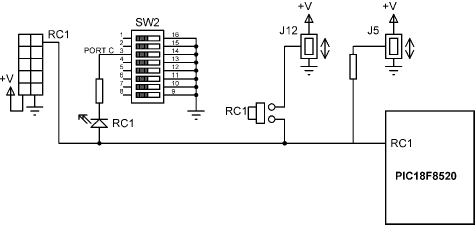
Figure 5.58: LED and push-button switch connections
The forty-six push-button switches on the board can be used to program digital inputs to the microcontroller. There is also a push-button switch that acts as the RESET. Jumper J12 determines whether a button press will bring logical 0 or logical 1 to the microcontroller. When the button is not pressed, the pin state is determined by jumper J5.
At the bottom central position, a 128?64 pixel graphics LCD can be connected to the board. The contrast of the LCD can be adjusted by a small potentiometer.
The MMC/SD card slot at the bottom right-hand corner of the board supports cards up to 2GB storage capacity.
The RESET button is located just above the MMC/SD card slot.
Above the RESET button are two potentiometers for analog-to-digital converter applications.
All of the microcontroller port pins are available at the connectors situated along the right-hand side of the board. In the top middle portion of the board are two RS232 ports and a connection to a PC keyboard.
The board supports both 64-pin and 80-pin microcontrollers. The board comes with a PIC18F8520 microcontroller connected to the board, operating with a 10MHz crystal. Further details about the operation of the board can be found in the BIGPIC4 user’s manual.
The steps in developing an application using the BIGPIC4 board are as follows:
Step 1 Double-click the mikroC icon to start the IDE.
Step 2 Create a new project called EXAMPLE2 (see Figure 5.59) and select the microcontroller type as PIC18F8520, the clock as 10MHz, and device flags as:
• _OSC_HS_1H
• _WDT_OFF_2H
• _LVP_OFF_4L
• _DEBUG_ON_4L
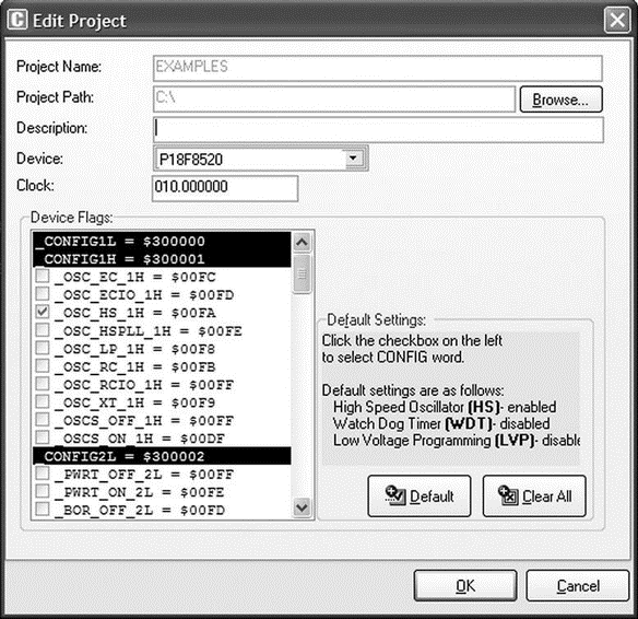
Figure 5.59: Creating a new project
Step 3 Enter the following program into the Code Editor section of the IDE:
/******************************************************************

                         EXAMPLE PROGRAM

This program uses the PICBIG4 Development Board. 8 LEDs are connected

to PORTC of the microcontroller which is a PIC18F8520 operating at 10MHz.

This program calculates the sum of integer numbers from 1 to 10

and then displays the sum on PORTC of the microcontroller.

Author: Dogan Ibrahim

File:   EXAMPLE2.C

****************************************************************/

void main() {

 unsigned int Sum,i;

 TRISC = 0;

 Sum = 0;

 for(i=1; i <= 10; i++) {

  Sum = Sum + i;

 }

 PORTC = Sum;

}
Step 4 Save the program with the name EXAMPLE2 by clicking File?Save As.
Step 5 Tick option ICD Debug in the Project Setup window. Compile the project by pressing CTRL+F9 or by clicking the Build Project button.
Step 6 Connect the BIGPIC4 development board to the USB port on the computer. Configure the development board by routing eight LEDs to PORTC: Set the arm marked PORTC on switch S2 to the ON position.
Step 7 Select Tools?PicFlash Programmer from the drop-down menu to program the microcontroller.
Step 8 Select Debugger?Select Debugger?mikroICD Debugger.
Step 9 Start the debugger by clicking Run?Start Debugger and select variables Sum, i, and PORTC from the Watch window.
Step 10 Single-step through the program until the end by repeatedly pressing F8. At the end of the program, the PORTC LEDs will turn ON to display decimal 55 (i.e., LEDs 0,1,2,4, and 5 will turn ON).
Step 11 Stop the debugger.
View the EEPROM Window The mikroICD EEPROM window is invoked from the mikroC IDE drop-down menu when the mikroICD debug mode is selected and started, and it displays contents of the PIC internal EEPROM memory. To view the memory, click View?Debug Windows?View EEPROM. Figure 5.60 shows an example EEPROM window display.
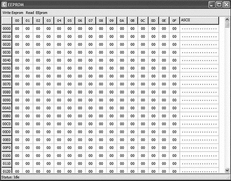
Figure 5.60: Display of EEPROM memory
View the RAM Window The mikroICD RAM window is invoked from the mikroC IDE drop-down menu when the mikroICD debug mode is selected and started, and it displays contents of the PIC internal RAM memory. To view the memory, click View?Debug Windows?View RAM. Figure 5.61 shows an example RAM window display.
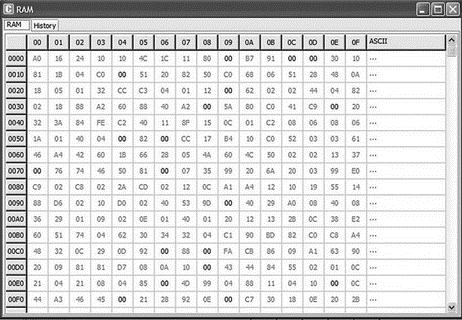
Figure 5.61: Display of RAM memory
View the Code Window The mikroICD Code window is invoked from the mikroC IDE drop-down menu when the mikroICD debug mode is selected and started, and it displays the contents of the PIC internal code memory. To view the memory, click View? Debug Windows?View Code. Figure 5.62 shows an example Code window display.
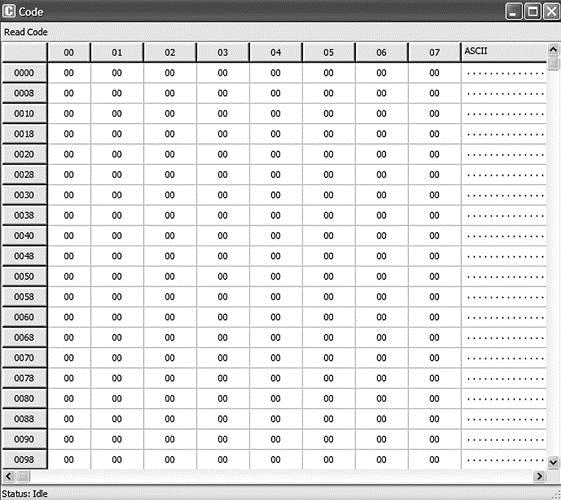
Figure 5.62: Display of Code memory
View the Statistics The Statistics window is invoked from the mikroC IDE dropdown menu and it displays various statistical data about our program. To view the statistics window, click View?View Statistics. Figure 5.63 shows an example Statistics window, which consists of several tabs. The Memory Usage tab displays the amount of RAM (data memory) and ROM (code memory) used. The Procedures tabs display information about the size and locations of the procedures. The RAM and ROM tabs display memory usage in detail.
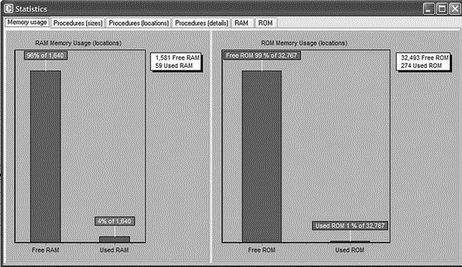
Figure 5.63: Display of Statistics window
- 2.2. Anatomy of an Embedded System
- 2.2.1. Typical Embedded Linux Setup
- 6.1.3. Minimal File System
- 7.5.3. Still More Bootloaders
- 10.3. MTD Partitions
- 16.2.1. Prerequisites and Assumptions
- 5.2.4 In-Circuit Emulators
- 5.3 mikroC Integrated Development Environment (IDE)
- 5.3.4 Using the mikroICD In-Circuit Debugger
- 3.4.1 Hardware Initialization
- 5.4.5 Creating a Target Eclipse Project
- Caveats using NAT
