Книга: Mastering VMware® Infrastructure3
Fibre Channel Storage
Разделы на этой странице:
Fibre Channel Storage
Despite its high cost, many companies rely on fibre channel storage as the backbone for critical data storage and management. The speed and security of the dedicated fibre channel storage network are attractive assets to companies looking for reliable and efficient storage solutions.
Understanding Fibre Channel Storage Networks
Fibre channel SANs can run at either 2GFC or 4GFC speeds and can be constructed in three different topologies: point-to-point, arbitrated loop, or switched fabric. The point-to-point fibre channel architecture involves a direct connection between the server and the fibre channel storage device. The arbitrated loop, as the name suggests, involves a loop created between the storage device and the connected servers. In either of these cases, a fibre channel switch is not required. Each of these topologies places limitations on the scalability of the fibre channel architecture by limiting the number of nodes that can connect to the storage device. The switched fabric architecture is the most common and offers the most functionality, so we will focus on it for the duration of this chapter and throughout the book. The fibre channel switched fabric includes a fibre channel switch that manages the flow of the SCSI communication over fibre channel traffic between servers and the storage device. Figure 4.10 displays the point-to-point and arbitrated loop architectures.
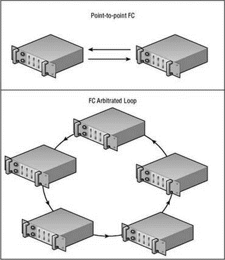
Figure 4.10 Fibre channel SANs can be constructed as point-to-point or arbitrated loop architectures.
The switched fabric architecture is more common because of its scalability and increased reliability. A fibre channel SAN is made up of several different components, including:
Logical unit numbers (LUNs) A logical configuration of disk space created from one or more underlying physical disks. LUNs are most commonly created on multiple disks in a RAID configuration appropriate for the disk usage. LUN design considerations and methodologies will be covered later in this chapter.
Storage device The storage device houses the disk subsystem from which the storage pools or LUNs are created.
Storage Processor (SP) One or more storage processors (SPs) provide connectivity between the storage device and the host bus adapters in the hosts. SPs can be connected directly or through a fibre channel switch.
Fibre channel switch A hardware device that manages the storage traffic between servers and the storage device. Although devices can be directly connected over fibre channel networks, it is more common to use a fibre channel switched network. The term fibre channel fabric refers to the network created by using fibre-optic cables to connect the fibre channel switches to the HBAs and SPs on the hosts and storage devices, respectively.
Host bus adapters (HBAs) A hardware device that resides inside a server that provides connectivity to the fibre channel network through a fibre-optic cable.
These SAN components make up the infrastructure that processes storage requests and manages the flow of traffic among the nodes on the network. Figure 4.11 shows a commonly configured fibre channel storage area network with two ESX Servers, redundant fibre channel switches, and a storage device.
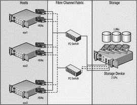
Figure 4.11 Most storage area networks consist of hosts, switches, and a storage device interconnected to provide servers with reliable and redundant access to storage pools residing in the storage device.
A SAN can be an expensive investment, predominantly because of the redundant hardware built into each of the segments of the SAN architecture. As shown in Figure 4.11, the hosts were outfitted with multiple HBAs connected to the fibre channel fabric, which consisted of multiple fibre channel switches connected to multiple storage processors in the storage device. The trade-off for the higher cost is less downtime in the event of a single piece of hardware failing in the SAN structure.
Now that we have covered the hardware components of the storage area network, it is important that, before moving into ESX specifics, we discuss how the different SAN components communicate with one another.
Each node in a SAN is identified by a globally unique 64-bit hexadecimal World Wide Name (WWN) or World Wide Port Name (WWPN) assigned to it. A WWN will look something like this:
22:00:00:60:01:B9:A7:D2
The WWN for a fibre channel node is discovered by the switch and is then assigned a port address upon login to the fabric. The WWN assigned to a fibre channel node is the equivalent of the globally unique Media Access Control (MAC) address assigned to network adapters on Ethernet networks.
Once the nodes are logged in and have been provided addresses they are free to begin communication across the fibre channel network as determined by the zoning configuration on the fibre channel switches. The process of zoning involves the configuration of a set of access control parameters that determine which nodes in the SAN architecture can communicate with other nodes on the network. Zoning establishes a definition of communication between storage processors in the storage device and HBAs installed on the ESX Server hosts. Figure 4.12 shows a fibre channel zoning configuration.
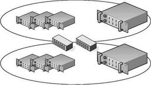
Figure 4.12 Zoning a fibre channel network at the switch level provides a security boundary that ensures that host devices do not see specific storage devices.
Zoning is a highly effective means of preventing non-ESX hosts from discovering storage volumes that are formatted as VMFS. This process effectively creates a security boundary between fibre channel nodes that simplifies management in large SAN environments. The nodes within a zone, or segment, of the network can communicate with one another but not with other nodes outside their zone. The zoning configuration on the fibre channel switches dictates the number of targets available to an ESX Server host. By controlling and isolating the paths within the switch fabric, the switch zoning can establish strong boundaries of fibre channel communication.
In most VI3 deployments, only one zone will be created since the VMotion, DRS, and HA features require all nodes to have access to the same storage. That is not to say that larger, enterprise VI3 deployments cannot realize a security and management advantage by configuring multiple zones to establish a segregation of departments, projects, or roles among the nodes. For example, a large enterprise with a storage area network that supports multiple corporate departments (i.e., marketing, sales, finance, and research) might have ESX Server hosts and LUNs for each respective department. In an effort to prevent any kind of cross-departmental LUN access, the switches can establish a zone for each department ensuring only the appropriate LUN access. Proper fibre channel switch zoning is a critical tool for separating a test or development environment from a production environment.
In addition to configuring zoning at the fibre channel switches, LUNs must be presented, or not presented, to an ESX Server. This process of LUN masking, or hiding LUNs from a fibre channel node, is another means of ensuring that a server does not have access to a LUN. As the name implies, this is done at the LUN level inside the storage device and not on the fibre channel switch. More specifically, the storage processor (SP) on the storage device allows for LUNs to be made visible or invisible to the fibre channel nodes that are available based on the zoning configuration. The hosts with LUNs that have been masked are not allowed to store or retrieve data from those LUNs.
Zoning provides security at a higher, more global level, whereas LUN masking is a more granular approach to LUN security and access control. The zoning and LUN masking strategies of your fibre channel network will have a significant impact on the functionality of your virtual infrastructure. You will learn in Chapter 9 that LUN access is critical to the advanced VMotion, DRS, and HA features of VirtualCenter.
Figure 4.13 shows a fibre channel switch fabric with multiple storage devices and LUNs configured on each storage device. Table 4.3 describes a LUN access matrix that could help a storage administrator and VI3 administrator work collaboratively on planning the zoning and LUN masking strategies.
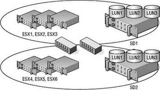
Figure 4.13 A fibre channel network consists of multiple hosts, multiple storage devices, and LUNs across each storage device. Every host does not always need access to every storage device or every LUN, so zoning and masking are a critical part of SAN design and configuration.
Fibre channel storage networks are synonymous with “high performance” storage systems. Arguably, this is in large part due to the efficient manner in which communication is managed by the fibre channel switches. Fibre channel switches work intelligently to reduce, if not eliminate, oversubscription problems in which multiple links are funnelled into a single link. Oversubscription results in information being dropped. With less loss of data on fibre channel networks, there is reduced need for retransmission of data and, in turn, processing power becomes available to process new storage requests instead of retransmitting old requests.
Configuring ESX for Fibre Channel Storage
Since fibre channel storage is currently the most efficient SAN technology, it is a common back-end to a VI3 environment. ESX has native support for connecting to fibre channel networks through the host bus adapter. However, ESX Server has limited support for the available storage devices and host bus adapters. Before investing in a SAN, make sure it is compatible and supported by VMware. Even if the SAN is capable of "working" with ESX, it does not mean VMware is going to provide support. VMware is very stringent with the hardware support for VI3; therefore, you should always implement hardware that has been tested by VMware.
Table 4.3: LUN Access Matrix
| Host | SD1 | SD2 | LUN1 | LUN2 | LUN3 |
|---|---|---|---|---|---|
| ESX1 | Yes | No | Yes | Yes | No |
| ESX2 | Yes | No | No | Yes | Yes |
| ESX3 | Yes | No | Yes | Yes | Yes |
| ESX4 | No | Yes | Yes | Yes | Yes |
| ESX5 | No | Yes | Yes | No | Yes |
| ESX6 | No | Yes | Yes | No | Yes |
Note: The processes of zoning and masking can be facilitated by generating a matrix that defines which hosts should have access to which storage devices and which LUNs.
Always check the compatibility guides before adding new servers, new hardware, or new storage devices to your virtual infrastructure.
Since VMware is the only company (at this time) that provides drivers for hardware supported by ESX, you must be cautious when adding new hardware like host bus adapters. The bright side, however, is that so long as you opt for a VMware-supported HBA, you can be certain it will work without incurring any of the driver conflicts or misconfiguration common in other operating systems.
VMware Fibre Channel SAN Compatibility
You can find a complete list of compatible SAN devices online on VMware's website at http://www.vmware.com/pdf/vi3_san_guide.pdf. Be sure to check the guides regularly as they are consistently updated. When testing a fibre channel SAN against ESX, VMware identifies compatibility in all of the following areas:
? Basic connectivity to the device.
? Multipathing capability for allowing access to storage via different paths.
? Host bus adapter (HBA) failover support for eliminating single point of failure at the HBA.
? Storage port failover capability for eliminating single point of failure on the storage device.
? Support for Microsoft Clustering Services (MSCS) for building server clusters when the guest operating system is Windows 2000 Service Pack 4 or Windows 2003.
? Boot-from-SAN capability for booting an ESX server from a SAN LUN.
? Point-to-point connectivity support for nonswitch-based fibre channel network configurations.
Naturally, since VMware is owned by EMC Corporation you can find a great deal of compatibility between ESX Server and the EMC line of fibre channel storage products (also sold by Dell). Each of the following vendors provides storage products that have been tested by VMware:
? 3PAR: http://www.3par.com
? Bull: http://www.bull.com
? Compellent: http://www.compellent.com
? Dell: http://www.dell.com
? EMC: http://www.emc.com
? Fujitsu/Fujitsu Siemens: http://www.fujitsu.com and http://www.fujitsu-siemens.com
? HP: http://www.hp.com
? Hitachi/Hitachi Data Systems (HDS): http://www.hitachi.com and http://www.hds.com
? IBM: http://www.ibm.com
? NEC: http://www.nec.com
? Network Appliance (NetApp): http://www.netapp.com
? Nihon Unisys: http://www.unisys.com
? Pillar Data: http://www.pillardata.com
? Sun Microsystems: http://www.sun.com
? Xiotech: http://www.xiotech.com
Although the nuances, software, and practices for managing storage devices across different vendors will most certainly differ, the concepts of SAN storage covered in this book transcend the vendor boundaries and can be used across various platforms.
Currently, ESX Server supports many different QLogic 236x and 246x fibre channel HBAs for connecting to fibre channel storage devices. However, because the list can change over time, you should always check the compatibility guides before purchasing and installing a new HBA.
It certainly does not make sense to make a significant financial investment in a fibre channel storage device and still have a single point of failure at each server in the infrastructure. We recommend that you build redundancy into the infrastructure at each point of potential failure. As shown in the diagrams earlier in the chapter, each ESX Server host should be equipped with a minimum of two fibre channel HBAs to provide redundant path capabilities in the event of HBA failure. ESX Server 3 supports a maximum of 16 HBAs per system and a maximum of 15 targets per HBA. The 16-HBA maximum can be achieved with four quad-port HBAs or eight dual-port HBAs provided that the server casing has the expansion capability.
Adding a new HBA requires that the physical server be turned off since ESX Server does not support adding hardware while the server is running, otherwise known as a ‘‘hot add’’ of hardware. Figure 4.14 displays the redundant HBA and storage processor (SP) configuration of a VI3 environment.
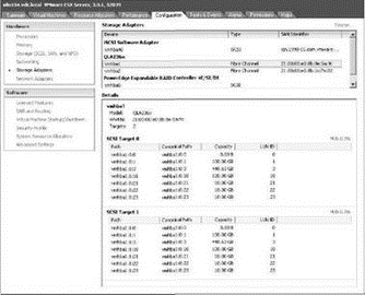
Figure 4.14 An ESX Server configured through Vir-tualCenter with two QLogic 236x fibre channel HBAs and multiple SCSI targets or storage processors (SPs) in the storage device.
Once fibre channel storage is presented to a server and the server recognizes the pools of storage, then the administrator can create datastores. A datastore is a storage pool on an ESX Server host that can be a local disk, fibre channel LUN, iSCSI LUN, or NFS share. A datastore provides a location for placing virtual machine files, ISO images, and templates.
For the VI3 administrator, the configuration of datastores on fibre channel storage is straightforward. It is the LUN masking, LUN design, and LUN management that incur significant administrative overhead (or more to the point, brainpower!). For VI3 administrators who are not responsible for SAN management and configuration, it is essential to work closely with the storage personnel to ensure performance and security of the storage pools used by the ESX Server hosts.
Later in this chapter we'll discuss LUN design in greater detail, but for now let's assume that LUNs have been created and masking has been performed. With those assumptions in place, the work required by the VI3 administrator is quick and easy. Figure 4.15 identifies five LUNs that are available to silo105.vdc.local through its redundant connection to the storage device. The ESX Server silo105.vdc.local has two HBAs connecting to a storage device, with two SPs creating redundant paths to the available LUNs. Although there are six LUNs in the targets list, the LUN with ID 0 is disregarded since it is not available to the ESX Server for storage.
A portion of the ESX Server boot process includes LUN discovery. An ESX Server, at boot-up and by default, will attempt to enumerate LUNs with LUN IDs between 1 and 255.
Even though silo105.vdc.local is presented with five LUNs, it does not mean that all five LUNs are currently being used to store data for the server. Figure 4.16 shows that silo105.vdc.local has three datastores, only two of which are LUNs presented by the fibre channel storage device. With two fibre channel SAN LUNs already in use, silo105.vdc.local has three more LUNs available when needed. Later in this chapter you'll learn how to use the LUNs as VMFS volumes.
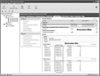
Figure 4.15 An ESX Server discovers its available LUNs and displays them under each available SCSI target. Here, five LUNs are available to the ESX Server for storage.

Figure 4.16 An ESX Server host with a local datastore named storage1 (2) and two datastores ISOTemps (1) and LUN10 on a fibre channel storage device.
When an ESX Server host is powered on, it will process the first 256 LUNs (LUN 0 through LUN 255) on the storage devices to which it is given access. ESX will perform this enumeration at every boot, even if many of the LUNs have been masked out from the storage processor side. You can configure individual ESX Server hosts not to scan all the way up to LUN 255 by editing the Disk.MaxLUN configuration setting. Figure 4.17 shows the default configuration of the Disk.MaxLUN value that results in accessibility to the first 256 LUNs.
LUN Masking at the ESX Server
Despite the potential benefit of performing LUN masking at the ESX Server (to speed up the boot process), the work necessary to consistently manage LUNs on each ESX Server may offset that benefit. 1 suggest that you perform LUN masking at the SAN.
To change the Disk.MaxLUN setting, perform the following steps:
1. Use the VI client to connect to a VirtualCenter Server or an individual ESX Server host.
2. Select the hostname in the inventory tree and select the Configuration tab in the details pane on the right.
3. In the Software section, click the Advanced Settings link.
4. In the Advanced Settings for <hostname> window, select the Disk option from the selection tree.
5. In the Disk.MaxLUN text box, enter the desired integer value for the number of LUNs to scan.
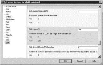
Figure 4.17 Altering the Disk.MaxLUN value can result in a faster boot or rescan process for an ESX Server host. However, it may also require attention when new LUNs must be made available that exceed the custom configuration.
You should alter the Disk.MaxLUN parameter only when you are certain that LUN IDs will never exceed the custom value. Otherwise, though a performance benefit might result, you will have to revisit the setting each time available LUN IDs must exceed the custom value.
Although LUN masking is most commonly performed at the storage processor, as it should be, it is also possible to configure LUN masking on each individual ESX Server host to speed up the boot process.
Let's take an example where an administrator configures LUN masking at the storage processor. Once the masking at the storage processor is complete, the LUNs that have been presented to the hosts are the ones numbered 117 through 127. However, since the default configuration for ESX Server is set to enumerate the first 256 LUNs by default, it will move through each potential LUN even if the storage processor is preventing the LUN from being seen. In an effort to speed up the boot process, an ESX Server administrator can perform LUN masking at the server. In this example, if the administrator were to mask LUN 1 through LUN 116 and LUN 128 through LUN 256, then the server would only be enumerating the LUNs that it is allowed to see and, as a result, would boot quicker. To enable LUN masking on an ESX Server, you must edit the Disk.MaskLUN option (which you access by clicking the Advanced Settings link on the Configuration tab). The Disk.MaskLUN text box requires this format:
<adapter>: <target>: <LUN range lists separated by commas>;
For example, to mask the LUNs from the previous example (1 through 116 and 128 through 256) that are accessible through the first HBA and two different storage processors, you'd enter the following in the Disk.MaskLUN text box entry:
vmhba1:0:1-116,128-256;vmhba1:1:1-116,128-256;
The downside to configuring LUN masking on the ESX Server is the administrative overhead involved when a new LUN is presented to the server or servers. To continue with the previous example, if the VI3 administrator requests five new LUNs and the SAN administrator provisions LUNs with LUN IDs of 136 through 140, the VI3 administrator will have to edit all of the local masking configurations on each ESX Server host to read as follows:
Vmhba1:0:1-116,128-135,141-254;vmhba1:1:1-116,128-135,141-256;
In theory, LUN masking on each ESX Server host sounds like it could be a benefit. But in practice, masking LUNs at the ESX Server in an attempt to speed up the boot process is not worth the effort. An ESX Server host should not require frequent reboots, and therefore the effect of masking LUNs on each server would seldom be felt. Additional administrative effort would be needed since each host would have to be revisited every time new LUNs are presented to the server.
ESX LUN Maximums
Be sure that storage administrators do not carve LUNs for an ESX Server that have ID numbers greater than 255. ESX hosts have a maximum capability of 256 LUNs, beginning with ID 1 and on through ID 255. Clicking the Rescan link located in the Storage Adapters node of the Configuration tab on a host will force the host to identify new LUNs or new VMFS volumes, with the exception that any LUNs with IDs greater than 255 will not be discoverable by an ESX host.
Although adding a new HBA to an ESX Server host requires you to shut down the server, presenting and finding new LUNs only requires that you initiate a rescan from the ESX Server host.
To identify new storage devices and/or new VMFS volumes that have been added since the last scan, click the Rescan link located in the Storage node of the Configuration tab. The host will launch an enumeration process beginning with the lowest possible LUN ID to the highest (1 to 255), which can be a slow process (unless LUN masking has been configured on the host as well as the storage processor).
You have probably seen by now, and hopefully agree, that VMware has done a great job of creating a graphical user interface (GUI) that is friendly, intuitive, and easy to use. Administrators also have the ability to manage LUNs from a Service Console command line on an ESX Server host.
The ability to scan for new storage is available in the VI Client using the Rescan link in the Storage Adapters node of the Configuration page, but it is also possible to rescan from a command line.
Establishing Console Access with Root Privileges
The root user account does not have secure shell (SSH) capability by default. You must set the Permit-RootLogin entry in the /etc/ssh/sshdconfig file to Yes to allow access. Alternatively, you can log on to the console as a different user and use the #su - option to elevate the logon permissions. Opting to use the #su - option still requires that you know the root user's password but does not expose the system to allowing remote root logon via SSH.
Use the following syntax to rescan vmhba1 from a Service Console command line:
1. Log on to a console session as a nonroot user.
2. Type su — and then click Enter.
3. Type the root user password and then click Enter.
4. Type esxcfg-rescan vmhba1 at the # prompt.
When multiple vmhba devices are available to the ESX Server, repeat the command, replacing vmhba# with each device.
You can identify LUNs using the physical address (i.e., vmhba#:target#:lun:partition), but the Service Console references the LUNs using the device filename (i.e., sda, sdb, etc.). You can see the device filenames when installing an ESX Server that is connected to a SAN with accessible LUNs. By using an SSH tool (putty.exe) to establish a connection and then issuing the esxcfg commands, you can perform command-line LUN management.
To display a list of available LUNs with their associated paths, device names, and UUIDs, perform the following steps:
1. Log on to a console session as a nonroot user.
2. Type su — and then click Enter.
3. Type the root user password and then click Enter.
4. Type esxcfg-vmhbadevs -m at the # prompt.
Figure 4.18 shows the resulting output for an ESX Server with an IP address of 172.30.0.106 and a nonroot user named roottoo.
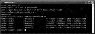
Figure 4.18 The esxcfg commands offer parameters and switches for managing and identifying LUNs available to an ESX Server host.
The UUIDs displayed in the output are unique identifiers used by the Service Console and VMkernel. These values are also reflected in the Virtual Infrastructure Client; however, we do not commonly refer to them because using the friendly names or even the physical paths is much easier.
Fibre channel storage has a strong performance history and will continue to progress in the areas of performance, manageability, reliability, and scalability. Unfortunately, the large financial investment required to implement a fibre channel solution has scared off many organizations looking to deploy a virtual infrastructure that offers all the VMotion, DRS, and HA bells that VI3 provides. Luckily for the IT community, VMware now offers lower-cost (and potentially lower-performance) options in iSCSI and NAS/NFS.
- 4.1 Сферы применения технологии Fibre Channel
- 8.1 Технология IP Storage
- iSCSI Network Storage
- Chapter 4 Creating and Managing Storage Devices
- Understanding VI3 Storage Options
- Understanding a Storage Area Network
- ESX Network Storage Architectures: Fibre Channel, iSCSI, and NAS
- Глава 8 Технологии IP Storage и InfiniBand
- 4.3 Преимущества Fibre Channel
- 4.4 Топологии Fibre Channel
- 4.5 Типы портов Fibre Channel
- 4.6 Протокол Fibre Channel
