Книга: Mastering VMware® Infrastructure3
Creating and Managing VMFS Datastores
Разделы на этой странице:
Creating and Managing VMFS Datastores
Microsoft has NTFS, Linux has EXT3, and so it is only fair that VMware have its own proprietary file system: VMFS. The VMware File System (VMFS) is a high-performance, distributed journaling file system used to house virtual machine files, ISO files, and templates in a VI3 environment. Any fibre channel, iSCSI, or local storage pool can be formatted as VMFS and used by an ESX Server host. Network storage located on NAS devices cannot be formatted as VMFS data-stores but still offer some of the same advantages. The VMFS found in the latest version of ESX Server is VMFS-3, which presents a significant upgrade from its predecessor VMFS-2.
VMFS protects against data integrity problems by writing all updates to a serial log on the disk before updating the original log. Postfailure, the server will restore the data to the prefailure state and recover any unsaved data by writing it to the intended prefailure location. Perhaps the most significant enhancement to VMFS-3 is its ability to have subdirectories, thus allowing virtual machine disk files to be located in respective folders under the VMFS volume parent label.
A VMFS volume stores all of the files needed by virtual machines, including:
? .vmx, the virtual machine configuration file.
? .vmx.lck, the virtual machine lock file created when a virtual machine is in a powered-on state.
? .nvram, the virtual machine BIOS.
? .vmdk, the virtual machine hard disk.
? .vmsd, the dictionary file for snapshots and the associated vmdk.
? .vmem, the virtual machine memory mapped to a file when the virtual machine is in a powered-on state.
? .vmss, the virtual machine suspend file created when a virtual machine is in a suspended state.
? -Snapshot#.vmsn, the virtual machine snapshot configuration.
? .vmtm, the configuration file for virtual machines in a team.
? -flat.vmdk, a pre-allocated disk file that holds virtual machine data.
? f001.vmdk, the first extent of pre-allocated disk files that hold virtual machine data split into 2GB files; additional files increment the numerical value.
? s001.vmdk, the first extent of expandable disk files that are split into 2GB files; additional files increment the numerical value.
? -delta.vmdk, the snapshot differences file.
VMFS is a clustered file system that allows multiple physical ESX Server hosts to simultaneously read and write to the same shared storage location. The block size of a VMFS volume can be configured as 1 MB, 2 MB, 4 MB, or 8 MB. Each of the block sizes corresponds to a maximum file size of 256GB, 512GB, 1024GB, and 2048GB, respectively.
2TB Limit?
Although the VMFS file system does not allow for files larger than 2048GB or 2TB, don't think of this as a limitation that prevents you from virtualizing specific servers. There might be scenarios in which large enterprise databases consume more than 2TB of space, but keep in mind that good file management practices should not have all of the data confined in a single database file. With the capabilities of Raw Device Mappings (RDMs), it is possible to virtualize even in situations where storage requirements exceed the 2TB limit that exists for a file on a VMFS volume.
To create a VMFS datastore on a fibre channel or iSCSI LUN using the VI Client, follow these steps:
1. Use the VI Client to connect to a VirtualCenter or an ESX Server host.
2. Select the hostname in the inventory panel and then click the Configuration tab.
3. Select Storage (SCSI, SAN, and NFS) from the Hardware menu.
4. Click the Add Storage link.
5. As shown in Figure 4.36, select the radio button labeled Disk/LUN and then click Next.
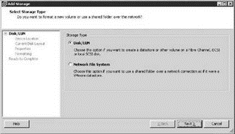
Figure 4.36 The Disk/LUN option in the Add Storage wizard formats allows you to configure a fibre channel or iSCSI SAN LUN as a VMFS volume.
6. As shown in Figure 4.37, select the appropriate SAN device for the VMFS datastore (i.e., vmhba1:0:21) and click Next.
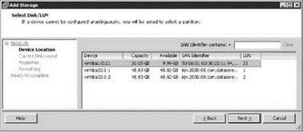
Figure 4.37 The list of SAN LUNs will include only the non-VMFS LUNs as available candidates for the new VMFS volume.
7. Click Next on the Current Disk Layout page.
8. Type a name for the new datastore in the Datastore Name text box and then click Next.
9. As shown in Figure 4.38, select a maximum file size and block size from the Maximum File Size drop-down list.
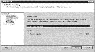
Figure 4.38 VMFS volumes can be configured to support a greater block size, which translates into greater file size capacity.
10. (Optional) If desired, though it's not recommended, the new VMFS datastore can be a portion of the full SAN LUN. Deselect the Maximize Capacity checkbox and specify a new size.
11. Review the VMFS volume configuration and then click Finish.
Don't Partition LUNs
When creating datastores, avoid partitioning LUNs. Use the maximum capacity of the LUN for each datastore created.
Although using the VI Client to create VMFS volumes through VirtualCenter is a GUI-oriented and simplified approach, it is also possible to create VMFS volumes from a command line using the fdisk and vmkfstools utilities. Perform these steps to create a VMFS volume from a command line:
1. Log in to a console session or use an application like Putty.exe to establish an SSH session to an ESX Server host.
2. Type the following command at the # prompt:
esxcfg-vmhbadevs
3. Determine if a valid partition table exists for the respective LUN by typing the following command at the # prompt:
fdisk -l /dev/sd?
where ? is the letter for the respective LUN. For example, /dev/sdf is shown in Figure 4.39.
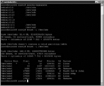
Figure 4.39 The esxcfg-vmhbadevs command identifies all the available LUNs for an ESX Server host; the fdisk -l /dev/sd? command will identify a valid partition table on a LUN.
4. To create a new partition on a LUN, type the following at a # prompt:
fdisk /dev/sd?
where ? is the letter for the respective LUN.
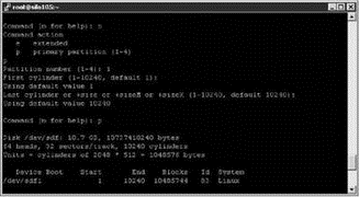
Figure 4.40 To create a VMFS volume from the command line, you must create a partition on the target LUN.
5. Type n to add a new partition.
6. Type p to create the partition as a primary partition.
7. Type 1 for a partition number of 1.
8. Press the Enter key twice to accept the default values for the first and last cylinders.
9. Type p to view the partition configuration. Steps 5 through 9 are displayed in Figure 4.40.
10. Once you've created the partition, define the partition type. At the Command (m for help) prompt, press the T key to enter the partition type.
11. At the Hex code prompt (type L to list codes), type fb to select the unknown code that corresponds to VMFS.
12. Type w to save the configuration changes. Figure 4.41 shows steps 10 through 12.
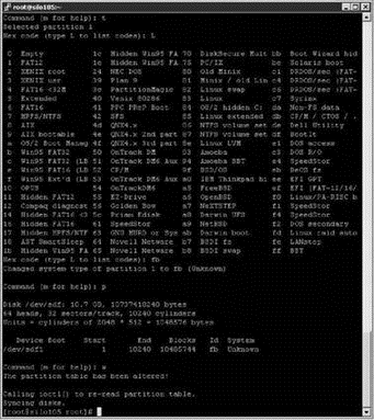
Figure 4.41 Once the partition is created, adjust the partition type to reflect the VMFS volume that will be created.
13. As shown in Figure 4.42, type the following command at the # prompt:
vmkfstools -C vmfs3 -S <VMFSNAME> vmhbaw:x:y:z
where <VMFSNAME> is the label to provide the VMFS volume, w is the HBA to use, x is the target ID for the storage processor, y is the LUN ID, and z is the partition.

Figure 4.42 After the LUN is configured, use vmkfstools to create the VMFS volume.
Aligning VMFS Volumes
Using the VI Client to create VMFS volumes will properly align the volume to achieve optimal performance in virtual environments with significant I/O. However, if you opt to create VMFS volumes using the command line, I recommend that you perform a few extra steps in the fdisk process to align the partition properly.
In the previous exercise insert the following steps between steps 11 and 12.
1. Type x to enter expert mode.
2. Type b to set the starting block number.
3. Type 1 to choose partition 1.
4. Type 128.
Note that the tests to identify the performance boosts were conducted against an EMC CX series storage area network device. The recommendations from VMware on alignment are consistent across fibre solutions and are not relevant for IP-based storage technologies. The tests concluded that proper alignment of the VMFS volume and the virtual machine disks produces increased throughput and reduced latency. Chapter 6 will list the recommended steps for aligning virtual machine file systems.
Once the VMFS volume is created, the VI Client provides an easy means of managing the various properties of the VMFS volume. The LUN properties offer the ability to add extents as well as to change the datastore name, the active path, and the path selection policy.
Adding extents to a datastore lets you increase the size of an extent greater than the 2TB limit. This does not allow file sizes to exceed the 2TB limit but only the size of the VMFS volume. Be careful when working with adding extents because the LUN that is added as an extent is wiped of all its data during the process. This can result in unintentional data loss. LUNs that are available as extent candidates are those that are not already formatted with VMFS, leaving empty or NTFS-formatted LUNS as viable candidates. (In other words, ESX will not eat its own!)
Adding VMFS Extents
When adding an extent to a VMFS volume, be sure to check for any existing data on the extent candidate. A simple method to do this is to compare the maximum size of the LUN with the available space to identify whether there is any existing data on the LUN. If the two sizes are almost identical, it is safe to say there is no data. For example, a 10GB LUN might reflect 9.99GB of free space. Check and double-check the LUNs. Since adding the extent will wipe all data from the extent candidate, you cannot be too sure.
While adding an extent through the VI Client or command line is an easy way to provide more space, it is a better practice to manage VMFS volume size from the storage device. To add an extent to an existing datastore, perform these steps:
1. Use the VI Client to connect to a VirtualCenter or an ESX Server host.
2. Select the hostname from the inventory pane and then click the Configuration tab.
3. Select Storage (SCSI, SAN, and NFS) from the Hardware menu.
4. Select the datastore to which the extent will be added.
5. Click the Properties link.
6. Click the Add Extent button, shown in Figure 4.43, on the datastore properties.
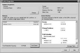
Figure 4.43 The properties page of a datastore lets you add an extent to increase the available storage space a datastore offers.
7. Choose an extent candidate on the Extent Device page of the Add Extent wizard, shown in Figure 4.44, and then click Next.
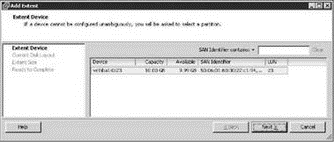
Figure 4.44 When adding an extent, be sure the selected extent candidate does not currently hold any critical data. All data is removed from an extent candidate when added to a datastore.
8. Click Next on the Current Disk Layout page.
9. (Optional) Although it is not recommended, the Maximum Capacity checkbox can be deselected and a custom value can be provided for the amount of space to use from the LUN.
10. Click Next on the Extent Size page.
11. Review the settings for the new extent and then click Finish.
12. Identify the new extent displayed in the Extents list and the new Total Formatted Capacity of the datastore, and then click Close.
13. As shown in Figure 4.45, identify the additional extent in the details pane for the datastore.
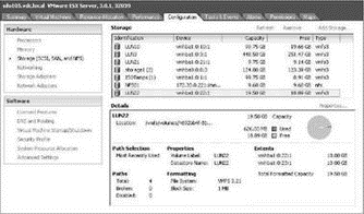
Figure 4.45 All extents for a datastore are reflected in the Total Formatted Capacity for the datastore and can be seen in the Extents section of the datastore details.
Once an extent is complete, the datastore will maintain the relationship until the datastore is removed from the host computer. An individual extent cannot be removed from a datastore.
Real World Scenario
Resizing a Virtual Machine's System Volume
The time will come when a critical virtual machine in your Windows environment will run out of space on the system volume. If you've been around Windows long enough, you know that it is not a fun issue to have to deal with. Though adding an extent can make a VMFS volume bigger, it does nothing to help this situation. There are third-party solutions to this problem; for example, use Symantec Ghost to create an image of the virtual machine and then deploy the image back to a new virtual machine with a larger hard drive. The solution described here comes completely at the hand of tools that are already available to you within ESX and Windows and will incur no financial charge.
As a first step to solving this problem, you must increase the size of the VMDK file that corresponds to the C drive. Using the vmkfstools command, you can expand the VMDK file to a new size. For example, to increase the size of a VMDK file named server1.vmdk from 20GB to 60GB:
1. Use the virtual machines properties to resize the virtual machine disk file size.
2. Mount the server1.vmdk file as a secondary drive in a different virtual machine.
3. Open a command window in the second virtual machine.
4. At the command prompt, type diskpart.exe.
5. To display the existing volumes, type list volume.
6. Type select volume <volume number>, where <volume number> is the number of the volume to extend.
7. To add the additional 40GB of space to the drive, type extend size=40000.
8. To quit diskpart.exe, type exit.
9. Shut down the second virtual machine to remove server1.vmdk.
10. Turn on the original virtual machine to reveal a new, larger C drive.
Free third-party utilities like QtParted and GParted can resize most types of file systems, including those from Windows and Linux. No matter which tool or procedure you use, be sure to always back up your VMDK before resizing.
If budget is not a concern, you can replace the mounting of the VMDK and use of the diskpart.exe utility with a third-party product like Acronis Disk Director. Disk Director is a graphical utility that simplifies managing volumes, even system volumes, on a Windows computer.
With the release of Windows Server 2008, Microsoft has now added the native ability to grow and shrink the system volume making it even easier to make these same types of adjustments without third part tools or fancy tricks.
All the financial, human, and time investment put into building a solid virtual infrastructure would be for nothing if ESX Server did not offer a way of ensuring accessing to VMFS volumes in the face of hardware failure. ESX Server has a native multipathing feature that allows for redundant access to VMFS volumes across an available path.
ESX Server Multipathing
ESX Server does not require third-party software, like EMC PowerPath, to gain the benefits of understanding and/or identifying redundant paths to network storage devices.
It doesn't seem likely that critical production systems with large financial investments in network storage would be left susceptible to single points of failure — which is why, in most cases, a storage infrastructure built to host critical data is done with redundancy at each level of the deployment. For example, a solid fibre channel infrastructure would include multiple HBAs per ESX host, connected to multiple fibre channel switches, connected to multiple storage processors on the storage device. In a situation where an ESX host has two HBAs and a storage device has two storage processors, there are four (2?2) different paths that can be assembled to provide access to LUNs. This concept, called multipathing, involves the use of redundant storage components to ensure consistent and reliable transfer of data. Figure 4.46 depicts a fibre channel infrastructure with redundant components at each level, which provides for exactly four distinct paths for accessing the available LUNs.
The multipathing capability built into ESX Server offers two different methods for ensuring consistent access: the most recently used (MRU) and the fixed path. As shown in Figure 4.47, the details section of an ESX datastore will identify the current path selection policy as well as the total number of available paths. The default policy, MRU, provides failover when a device is not functional but does not failback to the original device when the device is repaired. As the name suggests, an ESX host configured with an MRU policy will continue to transfer data across the most recently used path until that path is no longer available or is manually adjusted.
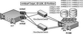
Figure 4.46 ESX Server has a native multipathing capability that allows for continued access to storage data in the event of hardware failure. With two HBAs and two storage processors, there exist exactly four paths that can be used to reach LUNs on a fibre channel storage device.
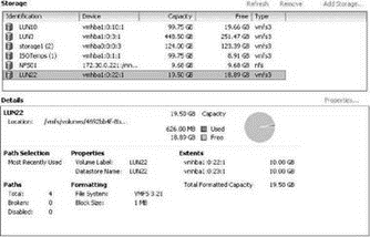
Figure 4.47 The Details of a datastore configured on a fibre channel LUN identifies the current path selection policy.
The second policy, fixed path, requires administrators to define the order of preference for the available paths. The fixed path policy, like the MRU, provides failover in the event that hardware fails, but it also provides failback upon availability of any preferred path as defined.
MRU vs. Fixed Path
Virtual infrastructure administrators should strive to spread the I/O loads over all available paths. An optimal configuration would utilize all HBAs and storage processors in an attempt to maximize data transfer efficiency. Once the path selections have been optimized, the decision will have to be made regarding the path selection policy. When comparing the MRU with fixed policies, you will find that each provides a set of advantages and disadvantages.
The MRU policy requires very little, if any, effort on the front end but requires an administrative reaction once failure (failover) has occurred. Once the failed hardware is fixed, the administrator must regain the I/O balance achieved prior to the failure.
The fixed path policy requires significant administrative overhead on the front end by requiring the administrator to define the order of preference. The manual path definition that must occur is a proactive effort for each LUN on each ESX Server host. However, after failover there will be an automatic failback, thereby eliminating any type of reactive steps on the part of the administrator.
Ultimately, it boils down to a ‘‘pay me now or pay me later’’ type configuration. Since hardware failure is not something we count on and is certainly something we hope happens on an infrequent basis, it seems that the MRU policy would require the least amount of administrative effort over the long haul.
Perform the following steps to edit the path selection policy for a datastore:
1. Use the VI Client to connect to a VirtualCenter or an ESX Server host.
2. Select the hostname in the inventory panel and then click the Configuration tab.
3. Select Storage (SCSI, SAN, and NFS) from the Hardware menu.
4. Select a datastore and review the details section.
5. Click the Properties link for the selected datastore.
6. Click the Manage Paths button in the Datastore properties box.
7. Click the Change button in the Policy section of the properties box.
8. As shown in Figure 4.48, select the Fixed radio button.
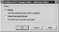
Figure 4.48 You can edit the path selection policy on a per-LUN basis.
9. Click OK.
10. Click OK.
11. Click Close.
Perform the following steps to change the active path for a LUN:
1. Use the VI Client to connect to a VirtualCenter or an ESX Server host.
2. Select the hostname in the inventory panel and then click the Configuration tab.
3. Select Storage (SCSI, SAN, and NFS) from the Hardware menu.
4. Select a datastore and review the details section.
5. Click the Properties link for the selected datastore.
6. Click the Manage Paths button in the Datastore properties box, shown in Figure 4.49.
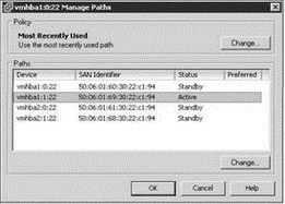
Figure 4.49 The Manage Paths detail box identifies the active and standby paths for a LUN and can be used to manually select a new active path.
7. Select the existing Active path and then click the Change button beneath the list of available paths.
8. Click the Disabled radio button to force the path to change to a different available path, shown in Figure 4.50.
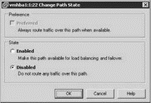
Figure 4.50 Disabling the active path of a LUN forces a new active path.
9. Repeat the process until the desired path is shown as the Active path.
Regardless of the LUN design strategy or multipathing policy put in place, virtual infrastructure administrators should take a very active approach to monitoring virtual machines to ensure that their strategies continue to maintain adequate performance levels.
- Chapter 4 Creating and Managing Storage Devices
- Разработка приложений баз данных InterBase на Borland Delphi
- Open Source Insight and Discussion
- Introduction to Microprocessors and Microcontrollers
- Chapter 6. Traversing of tables and chains
- Chapter 8. Saving and restoring large rule-sets
- Chapter 11. Iptables targets and jumps
- Chapter 5 Installing and Configuring VirtualCenter 2.0
- Chapter 16. Commercial products based on Linux, iptables and netfilter
- Appendix A. Detailed explanations of special commands
- Appendix B. Common problems and questions
- Appendix E. Other resources and links
