Книга: Mastering VMware® Infrastructure3
Creating and Managing NIC Teams
Разделы на этой странице:
In the previous section, we looked at some good examples of virtual network architectures needed to support the physical networking components. Now that you have some design and configuration basics under your belt, let's move on to extending the virtual networking beyond just establishing communication. A NIC team can support any of the connection types discussed in the previous section. Using NIC teams provides redundancy and load balancing of network communications to Service Console, VMkernel, and virtual machines.
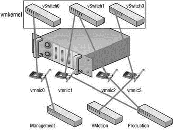
A NIC team, shown in Figure 3.20 and Figure 3.21, is defined as a vSwitch configured with an association to multiple physical network adapters (uplinks). As mentioned in the previous section, the ESX Server host can either have a maximum of 32 uplinks spread across multiple vSwitches or be configured as a NIC team on one vSwitch.
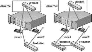
Successful NIC teaming requires that all uplinks be connected to physical switches that belong to the same broadcast domain. As shown in Figure 3.22, all of the physical network adapters in the NIC team should be connected to the same physical switch or to physical network adapters connected to physical switches that are connected to one another.

Figure 3.20 Virtual switches, like vSwitch1, with multiple uplinks offer redundancy and load balancing.

Figure 3.21 A NIC team is identified by the association of multiple physical network adapters assigned to a vSwitch.

Figure 3.22 All of the physical network adapters that make up a NIC team must belong to same Layer 2 broadcast domain.
Constructing NIC Teams
NIC teams should be built on physical network adapters located on separate bus architectures. For example, if an ESX Server host contains two on-board network adapters and a PCI-based quad-port network adapter, a NIC team should be constructed using one on-board network adapter and one network adapter on the PCI bus. This design eliminates a single point of failure.
Perform the following steps to create a NIC team using the VI Client:
1. Use the VI Client to establish a connection to a VirtualCenter server or an ESX Server host.
2. Click the hostname in the inventory panel on the left, select the Configuration tab from the details pane on the right, and then select Networking from the Hardware menu list.
3. Click the Properties for the virtual switch that will be assigned a NIC team and select the Network Adapters tab.
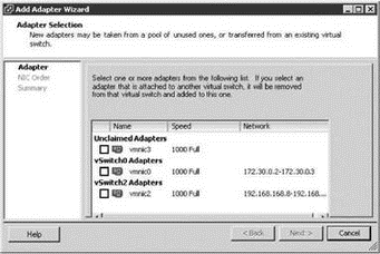
4. Click Add and select the appropriate adapter from the Unclaimed Adapters list, as shown in Figure 3.23.

Figure 3.23 Create a NIC team using unclaimed network adapters that belong to the same Layer 2 broadcast domain as the original adapter.
5. Adjust the Policy Failover Order as needed to support an Active/Standby configuration.
6. Review the summary of the virtual switch configuration, click Next, and then click Finish.
The load-balancing feature of NIC teaming does not function like the load-balancing feature of advanced routing protocols. Load balancing across a NIC team is not a product of identifying the amount of traffic transmitted through a network adapter and shifting traffic to equalize data flow through all available adapters. The load-balancing algorithm for NIC teams in a vSwitch is a balance of the number of connections — not the amount of traffic. NIC teams on a VI vSwitch can be configured with one of the following three load-balancing policies:
? vSwitch port-based load balancing (default)
? Source MAC-based load balancing
? IP hash-based load balancing
Outbound Load Balancing
The load-balancing feature of NIC teams on a vSwitch only applies to the outbound traffic.
- Разработка приложений баз данных InterBase на Borland Delphi
- Open Source Insight and Discussion
- Introduction to Microprocessors and Microcontrollers
- Chapter 6. Traversing of tables and chains
- Chapter 8. Saving and restoring large rule-sets
- Chapter 11. Iptables targets and jumps
- Chapter 5 Installing and Configuring VirtualCenter 2.0
- Chapter 16. Commercial products based on Linux, iptables and netfilter
- Appendix A. Detailed explanations of special commands
- Appendix B. Common problems and questions
- Appendix E. Other resources and links
- IP filtering terms and expressions


