Книга: Mastering VMware® Infrastructure3
Creating Virtual Switches and Port Groups
Разделы на этой странице:
- vSwitch Looping
- Virtual Switch Configuration Maximums
- Creating and Configuring Virtual Switches
- No Uplink, No VMotion
- Network Adapters and Network Discovery
- Uplink Limits
- Room to Grow
- Service Console Firewall
- Faster Communication Through the VMkernel
- Ports and Port Groups on a Virtual Switch
- Virtual Switch Configurations… Don't Go Too Big!
- Traffic Shaping as a Last Resort
Creating Virtual Switches and Port Groups
The answers to the following questions are an integral part of the design of your virtual networking:
? Do you have a dedicated network for Service Console management?
? Do you have a dedicated network for VMotion traffic?
? Do you have an IP storage network? iSCSI? NAS/NFS?
? How many NICs are standard in your ESX Server host design?
? Is the existing physical network comprised of vLANs?
? Do you want to extend the use of vLANs into the virtual switches?
As a precursor to the setup of a virtual networking architecture, the physical network components and the security needs of the network will need to be identified and documented.
Virtual switches in ESX Server are constructed and operated in the VMkernel. Virtual switches (also known as vSwitches) are not managed switches and do not provide all the advanced features that many new physical switches provide. These vSwitches operate like a physical switch in some ways, but in other ways they are quite different. Like their physical counterparts, vSwitches operate at Layer 2, support vLAN configurations, prevent overdelivery, forward frames to other switch ports, and maintain MAC address tables. Despite the similarities to physical switches, vSwitches do have some differences. A vSwitch created in the VMkernel cannot be connected to another vSwitch, thereby eliminating a potential loop configuration and the need to offer support for Spanning Tree Protocol (STP). In physical switches, STP offers redundancy for paths and prevents loops in the network topology by locking redundant paths in a standby state. Only when a path is no longer available will STP activate the standby path.
vSwitch Looping
Though the VMkernel does not allow looping because it does not allow vSwitches to be interconnected, it would be possible to manually create looping by connecting a virtual machine with two network adapters to two different vSwitches and then bridging the virtual network adapters. Since looping is a common network problem, it is a benefit for network administrators that vSwitches don't allow looping and prevent it from happening.
ESX Server allows for the configuration of three types of virtual switches. The type of switch is dependent on the association of a physical network adapter with the virtual switch. The three types of vSwitches, as shown in Figure 3.2 and Figure 3.3, include:
? Internal-only virtual switch
? Virtual switch bound to a single network adapter
? Virtual switch bound to two or more network adapters
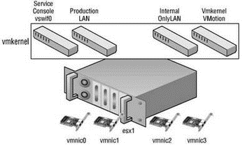
Figure 3.2 Virtual switches provide the cornerstone of virtual machine, VMkernel, and Service Console communication.
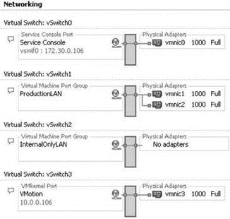
Figure 3.3 Virtual switches created on an ESX Server host manage all the different forms of communication required in a virtual infrastructure.
Virtual Switch Configuration Maximums
The maximum number of vSwitches for an ESX Server host is 127. Virtual switches created through the VI Client will be provided default names of vSwitch#, where # begins with 0 and increases sequentially to 127.
Creating and Configuring Virtual Switches
By default every virtual switch is created with 64 ports. However, only 56 of the ports are available and only 56 are displayed when looking at a vSwitch configuration through the Virtual Infrastructure client. Reviewing a vSwitch configuration via the esxcfg-vswitch command shows the entire 64 ports. The 8 port difference is attributed to the fact that the VMkernel reserves these 8 ports for its own use.
Once a virtual switch has been created the number of ports can be adjusted to 8, 24, 56, 120, 248, 504, or 1016. These are the values that are reflected in the Virtual Infrastructure client. But, as noted, there are 8 ports reserved and therefore the command line will show 32, 64, 128, 256, 512, and 1,024 ports for virtual switches.
Changing the number of ports in a virtual switch requires reboot of the ESX Server 3.5 host on which the virtual switch was altered.
Without an uplink, the internal-only vSwitch allows communication only between virtual machines that exist on the same ESX Server host. Virtual machines that communicate through an internal-only vSwitch do not pass any traffic through a physical adapter on the ESX Server host. As shown in Figure 3.4, communication between virtual machines connected to an internal-only switch takes place entirely in software and happens at whatever speed the VMkernel can perform the task.
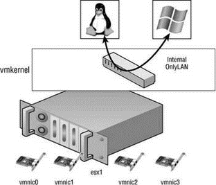
Figure 3.4 Virtual machines communicating through an internal-only vSwitch do not pass any traffic through a physical adapter.
No Uplink, No VMotion
Virtual machines connected to an internal-only vSwitch are not VMotion capable. However, if the virtual machine is disconnected from the internal-only vSwitch, a warning will be provided but VMotion will succeed if all other requirements have been met. The requirements for VMotion will be covered in Chapter 9.
For virtual machines to communicate with resources beyond the virtual machines hosted on the local ESX server, a vSwitch must be configured to use a physical network adapter, or uplink. A vSwitch bound to a single physical adapter allows virtual machines to establish communication with physical servers on the network, or with virtual machines on other ESX Server hosts that are also connected to a vSwitch bound to a physical adapter. The vSwitch associated with a physical network adapter provides virtual machines with the amount of bandwidth the physical adapter is configured to support. For example, a vSwitch bound to a network adapter with a 1Gbps maximum speed will provide up to 1Gbps worth of bandwidth for the virtual machines connected to it. Figure 3.5 displays the communication path for virtual machines connected to a vSwitch bound to a single network adapter. In the diagram, when VM01 on silo104 needs to communicate with VM02 on silo105, the traffic from the virtual machine is passed through the ProductionLAN virtual switch (port group) in the VMkernel on silo104 to the physical network adapter to which the virtual switch is bound. From the physical network adapter, the traffic will reach the physical switch (PhySw1). The physical switch (PhySw1) passes the traffic to the second physical switch (PhySw2), which will pass the traffic through the physical network adapter associated with the Production-LAN virtual switch on silo105. In the last stage of the communication, the virtual switch will pass the traffic to the destination virtual machine VM02.
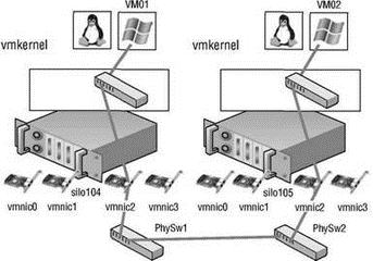
Figure 3.5 The vSwitch with a single network adapter allows virtual machines to communicate with physical servers and other virtual machines on the network.
Network Adapters and Network Discovery
Discovering the network adapters, and even the networks they are connected to, is easy with the VI Client. While connected to a VirtualCenter server or an individual ESX Server host, the Network Adapters node of the Configuration tab of a host will display all the available adapters. The following image shows how each adapter will be listed with information about the model of the adapter, the vmnic# label, the speed and duplex setting, its association to a vSwitch, and a discovery of the IP addresses it has found on the network:
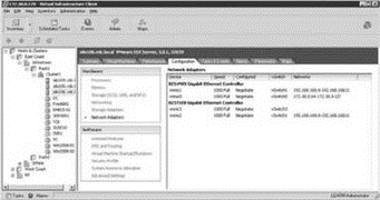
The network IP addresses listed under the Networks column are a result of a discovery across that network. The IP address range may change as new addresses are added and removed. For those NICs without a range, no IP addresses have been discovered. The network IP addresses should be used for information only and should be verified since they can be inaccurate.
The last type of virtual switch is referred to as a NIC team. As shown in Figure 3.6 and Figure 3.7, a NIC team involves the association of multiple physical network adapters with a single vSwitch. A vSwitch configured as a NIC team can consist of a maximum of 32 uplinks. In other words, a single vSwitch can use up to 32 physical network adapters to send and receive traffic from the physical switches. NIC teams offer the advantage of redundancy and load distribution. Later in this chapter, we will dig deeper into the configuration and workings of the NIC team.
Uplink Limits
Although a single vSwitch can be associated with multiple physical adapters as in a NIC team, a single physical adapter cannot be associated with multiple vSwitches. Pending the expansion capability, ESX Server 3.0.1 hosts can have up to 26 e100 network adapters, 32 e1000 network adapters, or 20 Broadcom network adapters. The maximum number of Ethernet ports on an ESX Server host is 32, regardless of the expansion slots or the number of adapters used to reach the maximum. For example, using eight quad-port NICs would achieve the 32-port maximum. All 32 ports could be configured for use by a single vSwitch or could be spread across multiple vSwitches.
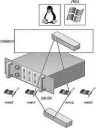
Figure 3.6 A vSwitch with a NIC team has multiple available adapters for data transfer. A NIC team offers redundancy and load distribution.

Figure 3.7 Virtual switches with a NIC team are identified by the multiple physical network adapters assigned to the vSwitch.
The vSwitch, as introduced in the first section of the chapter, allows several different types of communication, including communication to and from the Service Console, to and from the VMkernel, and between virtual machines. The type of communication provided by a vSwitch is dependent on the port (group), or connection type that is created on the switch. ESX Server hosts can have a maximum of 512 port groups, while the maximum number of ports (port groups) across all virtual switches is 4096.
Room to Grow
During the virtual network design I am often asked why virtual switches should not be created with the largest number of ports to leave room to grow. To answer this question let's look at some calculations against the network maximums of an ESX Server 3.5 host.
The maximum number of ports in a virtual switch is 1016. The maximum number of ports across all switches on a host is 4096. This means that if virtual switches are created with the 1016 port maximum only 4 virtual switches can be created. If you're doing a quick calculation of 1016 x 4 and realizing it is not 4096, don't forget that virtual switches actually have 8 reserved ports. Therefore, the 1016 port switch actually has 1,024 ports. Calculate 1,024 x 4 and you will arrive at the 4096 port maximum for an ESX Server 3.5 host.
Create virtual switches with a number of ports to meet your goals. If you can anticipate growth it will save you from a seemingly needless reboot in the future should you have to alter the virtual switch, but if it comes to it, that is why we are thankful for VMotion. Virtual machines can be moved to another host in order to satisfy the rebooting needs of tasks like editing the number of ports on a virtual switch.
Port groups operate as a boundary for communication and/or security policy configuration. Each port group includes functionality for a specific type of traffic but can also be used to provide more or less security to the traffic passing through the respective port group. There are three different connection types or port (groups), shown in Figure 3.8 and Figure 3.9, that can be configured on a vSwitch:
? Service Console port
? VMkernel port
? Virtual Machine port group
A Service Console port on a vSwitch, shown in Figure 3.10 and Figure 3.11, acts as a passage into the management and monitoring capabilities of the console operating system. The Service Console port, also called a vswif, requires that an IP address be assigned. The vSwitch with a Service Console port must be bound to the physical network adapter connected to the physical switch on the network from which management tasks will be performed. In Chapter 2, we covered how the ESX Server installer creates the first vSwitch with a Service Console port to allow postinstallation access.
Service Console Firewall
The console operating system (COS), or Service Console, includes a firewall that, by default, blocks all incoming and outgoing traffic except that required for basic server management. In Chapter 12 we will detail how to manage the firewall.
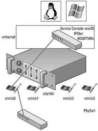
Figure 3.8 Virtual switches can contain three different connection types: Service Console, VMkernel, and virtual machine.
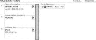
Figure 3.9 Virtual switches can be created with all three connection types on the same switch.
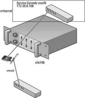
Figure 3.10 The Service Console port type on a vSwitch is assigned an IP address that can be used for access to the console operating system.

Figure 3.11 The Service Console port, known as a vswif, provides access to the console operating system.
A second Service Console connection provides redundancy in the form of a multihomed console operating system. This is not the same as a NIC team since this configuration will actually provide Service Console access on two different IP addresses. Perform the following steps to create a vSwitch with a Service Console connection using the VI Client:
1. Use the VI Client to establish a connection to a VirtualCenter server or an ESX Server host.
2. Click the hostname in the inventory panel on the left, select the Configuration tab from the details pane on the right, and then choose Networking from the Hardware menu list.
3. Click Add Networking to start the Add Network Wizard.
4. Select the Service Console radio button and click Next.
5. Select the checkbox that corresponds to the network adapter to be assigned to the vSwitch for Service Console communication, as shown in Figure 3.12.
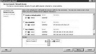
Figure 3.12 Adding a second vSwitch with a Service Console port creates a multi-homed Service Console with multiple entry points.
6. Type a name for the port in the Network Label text box.
7. Enter an IP address for the Service Console port. Ensure the IP address is a valid IP address for the network to which the physical NIC from step 5 is connected. You do not need a default gateway for the new Service Console port if a functioning gateway has already been assigned on the Service Console port created during the ESX Server installation process.
8. Click Next to review the configuration summary and then click Finish.
Perform the following steps to create a vSwitch with a Service Console port using the command line:
1. Use putty.exe or a console session to log in to an ESX Server and establish root-level permissions. Use su - to elevate to root or log in as root if permitted.
2. Use the following command to create a vSwitch named vSwitch:
esxcfg-vswitch -avSwitchX
3. Use the following command to create a port group named SCX to a vSwitch named vSwitchX:
esxcfg-vswitch -A SCX vSwitchX
4. Use the following command to add a Service Console NIC named vswif99 with an IP address of 172.30.0.204 and a subnet mask of 255.255.255.0 to the SCX port group created in step 3:
esxcfg-vswif --add --ip=172.30.0.204 --netmask=255.255.255.0 --portgroup=SCXvswif99
5. Use the following command to assign the physical adapter vmnic3 to the new vSwitch:
esxcfg-vswitch -L vmnic3 vSwitchX
6. Use the following command to restart the VMware management service:
service mgmt-vmware restart
The VMkernel port, shown in Figure 3.13 and Figure 3.14, is used for VMotion, iSCSI, and NAS/NFS access. Like the Service Console port, the VMkernel port requires the assignment of an IP address and subnet mask. The IP addresses assigned to VMkernel ports are needed to support the source-to-destination type IP traffic of VMotion, iSCSI, and NAS. Unlike with the Service Console, there is no need for administrative access to the IP addresses assigned to the VMkernel. In later chapters we will detail the iSCSI and NAS/NFS configurations, as well as the details of the VMotion process. These discussions will provide insight into the traffic flow between VMkernel and storage devices (iSCSI/NFS) or other VMkernels (for VMotion).
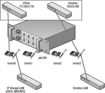
Figure 3.13 A VMkernel port created on a vSwitch is assigned an IP address that can be used for accessing iSCSI or NFS storage devices or for performing VMotion with another ESX Server host.
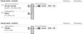
Figure 3.14 A VMkernel port is assigned an IP address and a port label. The label should identify the use of the VMkernel port.
Perform these steps to add a VMkernel port using the VI Client:
1. Use the VI Client to establish a connection to a VirtualCenter server or an ESX Server host.
2. Click the hostname in the inventory panel on the left, select the Configuration tab from the details pane on the right, and then choose Networking from the Hardware menu list.
3. Click Properties for the virtual switch to host the new VMkernel port.
4. Click the Add button, select the VMkernel radio button option, and click Next.
5. Type the name of the port in the Network Label text box.
6. Select Use This Port Group for VMotion if this VMkernel port will host VMotion traffic; otherwise, leave the checkbox unselected.
7. Enter an IP address for the VMkernel port. Ensure the IP address is a valid IP address for the network to which the physical NIC is connected. You do not need to provide a default gateway if the VMkernel does not need to reach remote subnets.
8. Click Next to review the configuration summary and then click Finish.
Follow these steps to create a vSwitch with a VMkernel port using the command line:
1. Use the following command to add a port group named VMkernel to a virtual switch named vSwitch0:
esxcfg-vswitch -A VMkernel vSwitch0
2. Use the following command to assign an IP address and subnet mask to the VMkernel port group:
esxcfg-vmknic -a -i 172.30.0.114 -n 255.255.255.0 VMkernel
3. Use the following command to assign a default gateway of 172.30.0.1 to the VMkernel port group:
esxcfg-route 172.30.0.1
4. Use the following command to restart the VMware management service:
service mgmt-vmware restart
The last connection type (or port group) to discuss is the Virtual Machine port group. The Virtual Machine port group is much different than the Service Console or VMkernel. Whereas both of the other port types require IP addresses for the source-to-destination communication that they are involved in, the Virtual Machine port group does not require an IP address. For a moment, forget about vSwitches and consider standard physical switches. Let's look at an example, shown in Figure 3.15, with a standard 16-port physical switch that has 16 computers connected and configured as part of the 192.168.250.0/24 IP network. The IP network provides for 254 valid IP addresses, but only 16 IP addresses are being used because the switch only has 16 ports. To increase the number of hosts that can communicate on the same logical IP subnet, a second switch could be introduced. To accommodate the second switch, one of the existing computers would have to be unplugged from the first switch. The open port on the first switch could then be connected to a second 16-port physical switch. Once the unplugged computer is reconnected to a port on the new switch, all 16 computers will once again communicate. In addition, there will be 15 open ports on the second switch to which new computers could be added.
A vSwitch created with a virtual machine port group bound to a physical network adapter that is connected to a physical switch acts just as the second switch did in the previous example. As in the physical switch to physical switch example, an IP address does not need to be configured for a virtual machine port group to combine the ports of a vSwitch with those of a physical switch. Figure 3.16 shows the switch-to-switch connection between a vSwitch and a physical switch.

Figure 3.15 Two physical switches can be connected to increase the number of available hosts on the IP network.
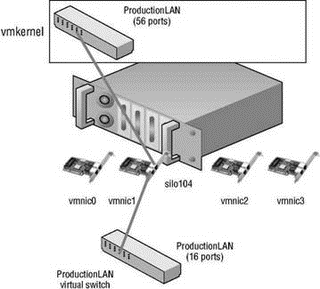
Figure 3.16 A vSwitch with a virtual machine port group uses an associated physical network adapter to establish a switch-to-switch connection with a physical switch.
Faster Communication Through the VMkernel
The virtual network adapter inside a guest operating system is not always susceptible to the maximum transmission speeds of the physical network cards to which the vSwitch is bound. Take, for example, two virtual machines, VM01 and VM02, both connected to the same vSwitch on an ESX Server host. When these two virtual machines communicate with each other, there is no need for the vSwitch to pass the communication traffic to the physical adapter to which it is bound. However, for VM01 to communicate with VM03 residing on a second ESX Server host, the communication must pass into the physical networking elements. The requirement of reaching into the physical network places a limit on the communication speed between the virtual machines. In this case, VM01 and VM03 would be limited to the 1Gbps bandwidth of the physical network adapter.
This image details how virtual machines communicating with one another through the same vSwitch are not susceptible to the bandwidth limits of a physical network adapter because there is no need for traffic to pass from the vSwitch to the physical adapter.
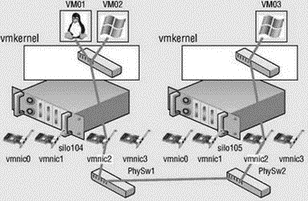
Although the guest operating systems of VM01 and VM02 will identify the virtual network adapters with speed and duplex settings, these settings are not apparent when VM01 and VM02 communicate with one another. This communication will take place at whatever speed the VMkernel can perform the operation. In other words, the communication is occurring in the host system's RAM and happens almost instantaneously as long as the VMkernel can allocate the necessary resources to make it happen. Even though uplinks might be associated with the vSwitch, the VMkernel neglects using the uplink to process the local traffic between virtual machines connected to the same vSwitch. Given that, there are advantages to ensuring that two virtual machines with a strong networking relationship remain on the same ESX Server host. Web servers or application servers that use back-end databases hosted on another server are prime examples of the type of networking relationship that can gain tremendous advantage from the efficient networking capability of the VMkernel.
Perform the following steps to create a vSwitch with a virtual machine port group using the VI Client:
1. Use the VI Client to establish a connection to a VirtualCenter server or an ESX Server host.
2. Click the hostname in the inventory panel on the left, select the Configuration tab from the details pane on the right, and then select Networking from the Hardware menu list.
3. Click Add Networking to start the Add Network Wizard.
4. Select the Virtual Machine radio button option and click Next.
5. Select the checkbox that corresponds to the network adapter to be assigned to the vSwitch. Select the NIC connected to the switch where production traffic will take place.
6. Type the name of the virtual machine port group in the Network Label text box.
7. Click Next to review the virtual switch configuration and then click Finish.
Follow these steps to create a vSwitch with a virtual machine port group using the command line:
1. Use the following command to add a virtual switch named vSwitch1:
esxcfg-vswitch -a vSwitch1
2. Use the following command to assign vSwitch1 to vmnic1:
esxcfg-vswitch -L vmnic1 vSwitch1
3. Use the following command to create a virtual machine port group named ProductionLAN on vSwitch1:
esxcfg-vswitch -A ProductionLAN vSwitch1
4. Use the following command to restart the VMware management service:
service mgmt-vmware restart
Ports and Port Groups on a Virtual Switch
A vSwitch can consist of multiple connection types, or each connection type can be created in its own vSwitch.
The creation of vSwitches and port groups and the relationship between vSwitches and uplinks is dependent on several factors, including the number of network adapters in the ESX Server host, the number of IP subnets to connect to, the existence of vLANs, and the number of physical networks to connect to. With respect to the configuration of the vSwitches and virtual machine port groups, there is no single correct configuration that will satisfy every scenario. It is true, however, to say that the greater the number of physical network adapters in an ESX Server host, the more flexibility you will have in your virtual networking architecture.
Later in the chapter we will discuss some advanced design factors, but for now let's stick with some basic design considerations. If the vSwitches created in the VMkernel are not going to be configured with multiple port groups or vLANs, you will be required to create a separate vSwitch for every IP subnet that you need to connect to. In Figure 3.17, there are five IP subnets that our virtual infrastructure components need to reach. The virtual machines in the production environment must reach the production LAN, the virtual machines in the test environment must reach the test LAN, the VMkernel needs to access the IP storage and VMotion LANs, and finally the Service Console must be on the management LAN. Notice that the physical network is configured with vLANs for the test and production LANs. They share the same physical network but are still separate IP subnets. Figure 3.17 displays a virtual network architecture that does not include the use of vLANs in the vSwitches and as a result requires one vSwitch for every IP subnet; five IP subnets means five vSwitches. In this case, each vSwitch consists of a specific connection type.
In this example, each connection type could be split because there were enough physical network adapters to meet our needs. Let's look at another example where an ESX Server host has only two network adapters to work with. Figure 3.18 shows a network environment with five IP subnets: management, production, test, IP storage, and VMotion, where the production, test, and IP storage networks are configured as vLANs on the same physical network. Figure 3.18 displays a virtual network architecture that includes the use of vLANs and that combines multiple connection types into a single vSwitch.
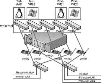
Figure 3.17 Without the use of port groups and vLANs in the vSwitches, each IP subnet will require a separate vSwitch with the appropriate connection type.
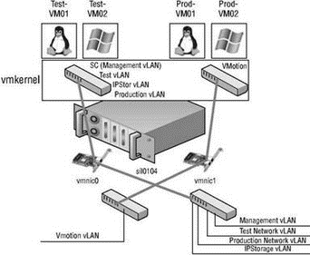
Figure 3.18 With a limited number of physical network adapters available in an ESX Server host, vSwitches will need multiple connection types to support the network architecture.
The vSwitch and connection type architecture of ESX Server, though robust and customizable, is subject to all of the following limits:
? An ESX Server host cannot have more than 4,096 ports.
? An ESX Server host cannot have more than 1,016 ports per vSwitch.
? An ESX Server host cannot have more than 127 vSwitches.
? An ESX Server host cannot have more than 512 virtual switch port groups.
Virtual Switch Configurations… Don't Go Too Big!
Although a vSwitch can be created with a maximum of 1,016 ports (really 1,024), it is not recommended if growth is anticipated. Because ESX Server hosts cannot have more than 4,096 ports (1,024?4), if vSwitches are created with 1,016 ports then only four vSwitches would be possible. Virtual switches should be created with just enough ports to cover existing needs and projected growth.
By default, all virtual network adapters connected to a vSwitch have access to the full amount of bandwidth on the physical network adapter with which the vSwitch is associated. In other words, if a vSwitch is assigned a 1Gbps network adapter, then each virtual machine configured to use the vSwitch has access to 1Gbps of bandwidth. Naturally, if contention becomes a bottleneck hindering virtual machine performance, a NIC team would be the best option. However, as a complement to the introduction of a NIC team, it is also possible to enable and to configure traffic shaping. Traffic shaping involves the establishment of hard-coded limits for a peak bandwidth, average bandwidth, and burst size to reduce a virtual machine's outbound bandwidth capability.
As shown in Figure 3.19, the peak bandwidth value and the average bandwidth value are specified in Kbps, and the burst size is configured in units of KB. The value entered for the average bandwidth dictates the data transfer per second across the virtual vSwitch. The peak bandwidth value identifies the maximum amount of bandwidth a vSwitch can pass without dropping packets. Finally, the burst size defines the maximum amount of data included in a burst. The burst size is a calculation of bandwidth multiplied by time. During periods of high utilization, if a burst exceeds the configured value packets will be dropped in favor of other traffic; however, if the queue for network traffic processing is not full, the packets will be retained for transmission at a later time.
Traffic Shaping as a Last Resort
Use the traffic shaping feature sparingly. Traffic shaping should be reserved for situations where virtual machines are competing for bandwidth and the opportunity to add network adapters is removed by limitations in the expansion slots on the physical chassis. With the low cost of network adapters, it is more worthwhile to spend time building vSwitch devices with NIC teams as opposed to cutting the bandwidth available to a set of virtual machines.
Perform the following steps to configure traffic shaping:
1. Use the VI Client to establish a connection to a VirtualCenter server or an ESX Server host.
2. Click the hostname in the inventory panel on the left, select the Configuration tab from the details pane on the right, and then select Networking from the Hardware menu list.
3. Click the Properties for the virtual switch, select the name of the virtual switch or port group from the Configuration list, and then click the Edit button.
4. Select the Traffic Shaping tab.
5. Select the Enabled option from the Status drop-down list.
6. Adjust the Average Bandwidth value to the desired number of Kbps.
7. Adjust the Peak Bandwidth value to the desired number of Kbps.
8. Adjust the Burst Size value to the desired number of KB.
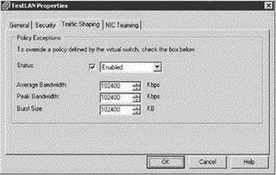
Figure 3.19 Traffic shaping reduces the outbound bandwidth available to a port group.
With all the flexibility provided by the different virtual networking components, you can be assured that whatever the physical network configuration may hold in store, there will be several ways to integrate the virtual networking. What you configure today may change as the infrastructure changes or as the hardware changes. Ultimately the tools provided by ESX Server are enough to ensure a successful communication scheme between the virtual and physical networks.
- Chapter 3 Creating and Managing Virtual Networks
- Разработка приложений баз данных InterBase на Borland Delphi
- Open Source Insight and Discussion
- Introduction to Microprocessors and Microcontrollers
- Chapter 6. Traversing of tables and chains
- Chapter 8. Saving and restoring large rule-sets
- Chapter 11. Iptables targets and jumps
- Chapter 5 Installing and Configuring VirtualCenter 2.0
- Chapter 16. Commercial products based on Linux, iptables and netfilter
- Appendix A. Detailed explanations of special commands
- Appendix B. Common problems and questions
- Appendix E. Other resources and links
