Книга: Embedded Linux development using Eclipse
8.1.5 Sequence Diagram
8.1.5 Sequence Diagram
To round out our brief tour of EclipseUML, we’ll create a sequence diagram to describe the system’s response to the passenger pushing an UpDownButton. The sequence is as follows:
1. The passenger presses an UpDownButton.
2. The UpDownButton sends an update to the Controller.
3. The Controller illuminates the button and moves the Elevator to the specified floor.
4. The Elevator signals that it has reached the floor.
5. The Controller stops the Elevator and turns off the UpDownButton illumination.
6. The Controller opens the Door.
7. After a suitable delay, the Controller closes the Door.
Right-click the elevator package and select New UML Diagram?UML Sequence Diagram. Name it “UpDownButtonSequence” and store it in the models/ directory. The Sequence Diagram editor tool bar (Figure 8.11) has the following buttons:
• Selection mode
• Zoom mode
• Add new property (similar to add an object)
• Create an actor
• Add a message
• Add a self message
• Add a frame
• Add an Interaction Use
• Create a Component
• Create a Class
• Create an Interface
• Create an entity
• Create a boundary
• Create a controller
• Create a note
• Create an indication
• Create a diagram link
• Create a text label

Figure 8.11: Sequence Diagram editor tool bar.
For the purpose of this illustration we’ll only be using a couple of these buttons, Create an actor and Add a message. Our objective here is to express the interactions among the classes in our system for the Press up/down button use case. Begin by creating an actor in the upper left-hand corner of the diagram and name it “passenger.”
Now the cool thing is that we can drag the classes from the elevator package in the Package Explorer view directly into the sequence diagram. Drag the classes so they show up in the following order to the right of the passenger:
1. UpDownButton
2. Controller
3. Elevator
4. Door
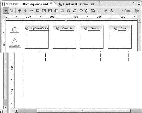
In order to get the Door class to show up you may have to maximize the editor window and drag the frame out to about 700 pixels. Then restore the editor to its windowed view. Your diagram should now look something like Figure 8.12. Each of the boxes is an instance of its respective class.

Figure 8.12: Sequence diagram with classes.
Note that the Outline view shows a thumbnail of the entire diagram with the portion visible in the Editor shaded. You can drag the shaded portion to scroll around in the Editor.
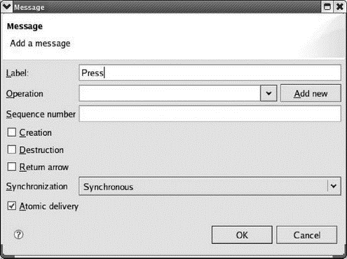
In the context of a sequence diagram, classes communicate by sending messages to each other. Click the Add a message button, move the cursor to just below the label of the actor (his head turns blue) and click. Now move the cursor to the right until the UpDownButton box turns blue, and click. The Message dialog of Figure 8.13 comes up. Label it “Press.”

Figure 8.13: Message dialog.
Here you can also specify the Operation (method) that carries out the message. In this case, of course, there is none — the passenger is pressing the button. The commercial version of EclipseUML will add method templates to the class code. Leave the rest of the fields at their default values and click OK.
In like fashion, add a message labeled “update” from the UpDownButton to the Controller. You might want to grab the vertical box below the controller and drag it down a little to make it clear that the update follows the press. Next add a message from the Controller back to the UpDownButton and label it “illuminate.”
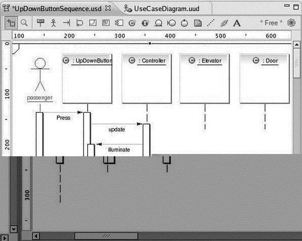
This gets a little tricky. The destination of a message can’t be the vertical bar (known as an “activation”) below a class instance. Note that when you drag the message wire over the activation bar, the international “no” symbol pops up. Drag the wire until the UpDownButton box is shaded blue, and click. Again, you’ll probably want to drag down the activation bar at the end of the illuminate message for readability. Your diagram should now look something like Figure 8.14.

Figure 8.14: Sequence diagram with messages.
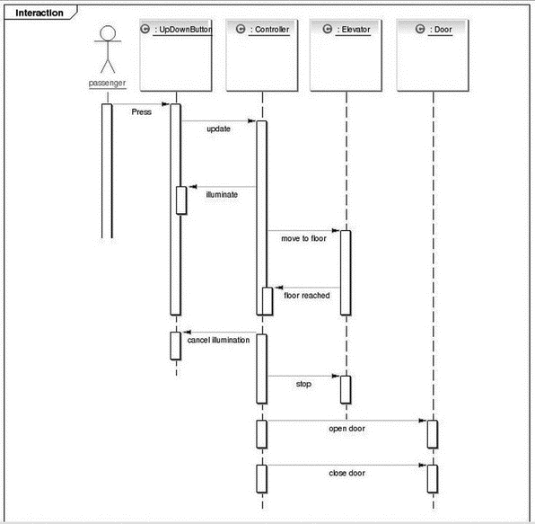
Continue adding messages to carry out the sequence of events listed above. After illuminating the button, the Controller will start the Elevator moving toward the specified floor. The Elevator will notify the Controller when it has reached the floor, whereupon the Controller will stop the Elevator and turn off the button illumination. Finally the Controller opens the Door and, after a suitable delay, closes the Door. The final diagram is shown in Figure 8.15.

Figure 8.15: Completed sequence diagram.
Unfortunately, EclipseUML seems to have a mind of its own when it comes to vertical spacing of messages. It seems that some activation bars can be moved and resized, while other can’t. The resulting diagram is so big it requires a full screen to display.
We could continue looking at the other UML diagrams, but I think you get the idea. Feel free to play around with them and see what they do.
- Sequence number
- Escape Sequences
- 3.1.9 Escape Sequences
- 8.1.3 Use Case Diagram
- Be Paranoid: Call Sequence Checks
- 3.4 Target System Software Initialization Sequence
- Sequence
- 1.5.1. Диаграммы потоков данных (Data Flow Diagramming)
- 1.4.1. Диаграммы потоков данных (Data Flow Diagramming)
- Vectors As Sequences
- Sequence Iterating Functions
- Whole Sequence Manipulations


