Книга: Introduction to Microprocessors and Microcontrollers
A truth table
A truth table
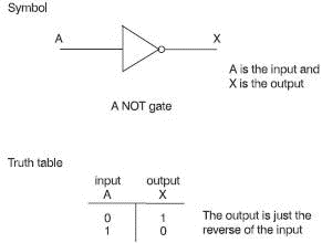
This is an alternative to the wordy description of how a gate works. It simply lists all the possible inputs to the gate together with the corresponding outputs. The truth table for a NOT gate is really easy. There are only two possible inputs: 0 and 1 as we can see in Figure 5.2.

Figure 5.2 The truth table for a NOT gate
So, how is it used in the microprocessor?
The truth table only shows what happens to a single bit but in the microprocessor we may want to use a NOT gate to invert a hex number like A4H. In this case the hex number is first converted to an 8-bit binary number. This process is not performed by the microprocessor but by other external circuits. By the time it reaches the microprocessor it has been converted to the binary equivalent of 101001002.
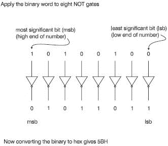
The NOT gate has only one input so, to handle an 8-bit binary word, we will need eight NOT gates. Now it becomes much easier. Each NOT gate inverts just one of the bits and all the outputs are grouped together to form a new hex number. See how it works in Figure 5.3. The result was the hex number 5BH. This is curious. If we add A4H to this result of 5BH we get FFH or all ‘ones’ in binary, 111111112. There was nothing special about the number A4H. It happens with any pair of numbers generated by NOT gates. Why is this? Figure 5.3 gives a clue.

Figure 5.3 Inverting a hex number
A little extra bit
We can show an inversion by drawing a line over the top. In Figure 5.2 the input was given the letter A and the output was shown as X. We could say: X=

- 9.9.8 CAN Message Reception
- 4. Syntax and Semantics
- Logical Operators
- Приложение 5 ТЗ на дизайн и верстку e-mail шаблона Чек?лист на подготовку рассылки
- 5. An introduction to logic gates and their uses
- The XNOR (or ENOR) gate
- AND, OR, and NOT
- equal_to
- greater_equal
- The NOT gate
- AND gate
- The NAND gate


