Книга: Introduction to Microprocessors and Microcontrollers
Simple test equipment
Simple test equipment
Apart from the standard voltmeter and an oscilloscope the only other simple piece of gear that may be helpful is the logic probe. It is better than the average oscilloscope at detecting very short voltage spikes and is faster to work with than a voltmeter.
Logic probe
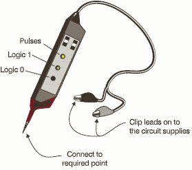
A logic probe is a simple instrument that has two power connections and the other is a conducting tip that can be touched on points of interest. The general layout is shown in Figure 18.4. There are three LEDs on it. The first two show the logic states 0 or 1 and the third one indicates the presence of a high frequency square-wave or a single, very short duration, pulse, called a ‘glitch’.

Figure 18.4 A logic probe
Simple tests to make with these pieces of test gear
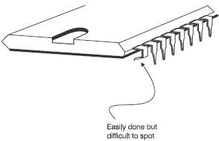
We can check some of the voltages on the microprocessor pins. If possible, it is a good idea to check on the actual pins rather than the base into which it is plugged. Doing this ensures that the base connections are also OK. It would also find the bent pin shown in Figure 18.5.

Figure 18.5 Pin bending not recommended
The likely pins that are worth checking are the ones carrying a dc voltage like the power supplies and the interrupts. It is worth keeping an eye on pins that should be at 0 V. When using a voltmeter, they can sometimes show 0 V when they are disconnected and floating. If you use your voltmeter to measure the voltage between the positive supply voltage and the suspect pin, it will still indicate 0 V showing that something is clearly amiss. A logic probe would not be fooled by a floating ‘zero’, it will not show a logic zero if it is floating.
The next job is to see if the microprocessor is running at all. We can do this by using the oscilloscope on a clock signal. Assuming that the clock signal is OK, we must next check that the microprocessor can follow an instruction and that the address and data bus are being read correctly.
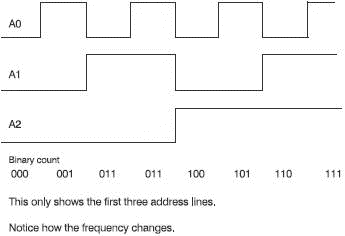
A good check on the operation of the microprocessor can be arranged by getting it to do a simple repetitive program consisting of a permanent ‘no operation’ code. A no-operation code will instruct the microprocessor to do nothing except read the next instruction from the data bus by simply incrementing the value on the address bus. This new instruction will be another no-operation code and so the address bus will be continuously incremented. To provide a permanent no-op input we can solder or otherwise connect the required logic codes to the data bus. This is called hard-wiring the data bus. As the address bus counts up in binary the lowest address line will be switching rapidly between zero and one giving a square wave output.
If we look at Figure 18.6, we can see that line A1 is running at half the frequency of line A0. Similarly address line A2 has half the frequency of A1 and so on all the way along the address pins. If we connect an oscilloscope to each line in turn, the frequency should reduce steadily. Check for the halving of frequency on each address line and errors in wiring like short circuits between address lines will become apparent.

Figure 18.6 The address bus counts up in binary
If we get this far and still things seem wrong, we are into serious faultfinding.
- Running the Test
- 18. Test equipment and fault-finding
- A serious piece of test equipment
- Листинг 10.1. (simpleid.c) Отображение идентификаторов пользователя и группы
- rc.test-iptables.txt
- Example rc.test-iptables script
- Testing the Project
- Testing Wdm2 Power Capabilities
- Test Driver Code
- The Simplest Windows Program
- Тестовые данные (Test Data)
- Testing Samba with the testparm Command


