Книга: Advanced PIC Microcontroller Projects in C
7.1 The SD Card
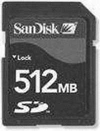
Before going into the design details of SD card–based projects, we should take a look at the basic principles and operation of SD card memory devices. Figure 7.1 shows a typical SD card.

Figure 7.1: A typical SD card
The SD card is a flash memory storage device designed to provide high-capacity, nonvolatile, and rewritable storage in a small size. These devices are frequently used in many electronic consumer goods, such as cameras, computers, GPS systems, mobile phones, and PDAs. The memory capacity of the SD cards is increasing all the time. Currently they are available at capacities from 256MB to 8GB. The SD cards come in three sizes: standard, mini, and micro. Table 7.1 lists the main specifications of the most common standard SD and miniSD cards.
Table 7.1: Standard SD and miniSD cards
| Standard SD | miniSD | |
|---|---|---|
| Dimensions | 32 ? 24 ? 2.1mm | 21.5 ? 20 ? 1.4mm |
| Card weight | 2.0 grams | 1.0 grams |
| Operating voltage | 2.7–3.6V | 2.7–3.6V |
| Write protect | yes | no |
| Pins | 9 | 11 |
| Interface | SD or SPI | SD or SPI |
| Current consumption | <75mA (Write) | <40mA (Write) |
SD card specifications are maintained by the SD Card Association, which has over six hundred members. MiniSD and microSD cards are electrically compatible with the standard SD cards and can be inserted in special adapters and used as standard SD cards in standard card slots.
SD card speeds are measured three different ways: in KB/s (kilobytes per second), in MB/s (megabytes per second), in an “x” rating similar to that of CD-ROMS where “x” is the speed corresponding to 150KB/s. The various “x” based speeds are:
• 4x: 600KB/s
• 16x: 2.4MB/s
• 40x: 6.0MB/s
• 66x: 10MB/s
In this chapter we are using the standard SD card only. The specifications of the smaller SD cards are the same and are not described further in this chapter.
SD cards can be interfaced to microcontrollers using two different protocols: SD card protocol and the SPI (Serial Peripheral Interface) protocol. The SPI protocol, being more widely used, is the one used in this chapter. The standard SD card has 9 pins with the pin layout shown in Figure 7.2. The pins have different functions depending on the interface protocol. Table 7.2 gives the function of each pin in both the SD and SPI modes of operation.

Figure 7.2: Standard SD card pin layout
Table 7.2: Standard SD card pin definitions
| Pin | Name | SD description | SPI description |
|---|---|---|---|
| 1 | CD/DAT3/CS | Data line 3 | Chip select |
| 2 | CMD/Datain | Command/response | Host to card command and data |
| 3 | VSS | Supply ground | Supply ground |
| 4 | VDD | Supply voltage | Supply voltage |
| 5 | CLK | Clock | Clock |
| 6 | VSS2 | Supply voltage ground | Supply voltage ground |
| 7 | DAT0 | Data line 0 | Card to host data and status |
| 8 | DAT1 | Data line 1 | Reserved |
| 9 | DAT2 | Data line 2 | Reserved |
Since the SD card projects described in this chapter are based on the SPI bus protocol, it is worth looking at the specifications of this bus before proceeding to the projects themselves.
- Example NAT machine in theory
- Elements of the xorg.conf File
- Managing Files with the Shell
- Sound Cards
- Using xconfig to Configure the Kernel
- 7.1.2 Operation of the SD Card in SPI Mode
- PROJECT 7.3 — Using the Card Filing System
- Inserting the Card
- What is needed to build a NAT machine
- modinfo
- Configuring X
- TV and Video Hardware


