Книга: Mastering VMware® Infrastructure3
Cluster-Across-Boxes
Разделы на этой странице:
Cluster-Across-Boxes
While the cluster-in-a-box scenario is more of an experimental or education tool for clustering, the cluster-across-boxes configuration provides a solid solution for critical virtual machines with stringent uptime requirements — for example, the enterprise-level servers and services like SQL Server and Exchange Server that are heavily relied on by the bulk of the end-user community. The cluster-across-boxes scenario, as the name applies, draws its high availability from the fact that the two nodes in the cluster are managed on different ESX Server hosts. In the event that one of the hosts fails, the second node of the cluster will assume ownership of the cluster group, and its resources and the service or application will continue responding to client requests.
The cluster-across-boxes configuration requires that virtual machines have access to the same shared storage, which must reside on a storage device external to the ESX Server hosts where the virtual machines run. The virtual hard drives that make up the operating system volume of the cluster nodes can be a standard VMDK implementation; however, the drives used as the shared storage must be set up as a special kind of drive called a raw device mapping. The raw device mapping is a feature that allows a virtual machine to establish direct access to a LUN on a SAN device.
Raw Device Mappings (RDMs)
A raw device mapping (RDM) is not direct access to a LUN, nor is it a normal virtual hard disk file. An RDM is a blend between the two. When adding a new disk to a virtual machine, as you will soon see, the Add Hardware Wizard presents the Raw Device Mappings as an option on the Select a Disk page. This page defines the RDM as having the ability to give a virtual machine direct access to the SAN, thereby allowing SAN management. I know this seems like a contradiction to the opening statement of this sidebar; however, we're getting to the part that oddly enough makes both statements true.
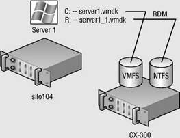
By selecting an RDM for a new disk, you're forced to select a compatibility mode for the RDM. An RDM can be configured in either Physical Compatibility mode or Virtual Compatibility mode. The Physical Compatibility mode option allows the virtual machine to have direct raw LUN access. The Virtual Compatibility mode, however, is the hybrid configuration that allows raw LUN access but only through a VMDK file acting as a proxy. The image shown here details the architecture of using an RDM in Virtual Compatibility mode:
So why choose one over the other if both are ultimately providing raw LUN access? Since the RDM in Virtual Compatibility mode uses a VMDK proxy file, it offers the advantage of allowing snapshots to be taken. By using the Virtual Compatibility mode, you will gain the ability to use snapshots on top of the raw LUN access in addition to any SAN-level snapshot or mirroring software. Or, of course, in the absence of SAN-level software, the VMware snapshot feature can certainly be a valuable tool. The decision to use Physical Compatibility or Virtual Compatibility is predicated solely on the opportunity and/or need to use VMware snapshot technology.
A cluster-across-boxes requires a more complex setup than the cluster-in-a-box scenario. When clustering across boxes, all proper communication between virtual machines and all proper communication from virtual machines and storage devices must be configured properly. Figure 10.4 provides details on the setup of a two-node virtual machine cluster-across-boxes using Windows Server 2003 guest operating systems.
Perform the following steps to configure Microsoft Cluster Services across virtual machines on separate ESX Server hosts.
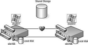
Figure 10.4 A Microsoft cluster built on virtual machines residing on separate ESX hosts requires shared storage access from each virtual machine using a raw device mapping (RDM).
Creating the First Cluster Node
To create the first cluster node, follow these steps:
1. Create a virtual machine that is a member of a Windows Active Directory domain.
2. Right-click the new virtual machine and select the Edit Settings option.
3. Click the Add button and select the Hard Disk option.
4. Select the Raw Device Mappings radio button option, as shown in Figure 10.5, and then click the Next button.
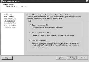
Figure 10.5 Raw device mappings allow virtual machines to have direct LUN access.
5. Select the appropriate target LUN from the list of available targets, as shown in Figure 10.6.
6. Select the datastore location, shown in Figure 10.7, where the VMDK proxy file should be stored, and then click the Next button.
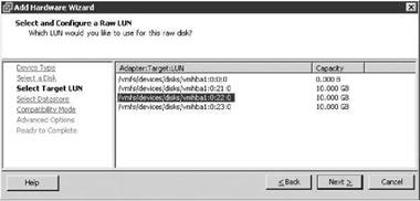
Figure 10.6 The list of available targets includes only the LUNs not formatted as VMFS.
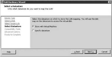
Figure 10.7 By default the VMDK file that points to the LUN is stored in the same location as the existing virtual machine files.
Select the Virtual radio button option to allow VMware snapshot functionality for the raw device mapping, as shown in Figure 10.8. Then click Next.
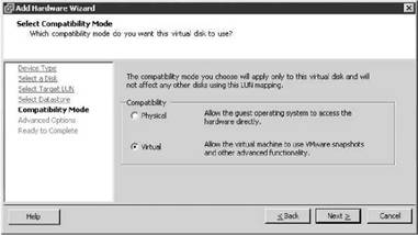
Figure 10.8 The Virtual Compatibility mode enables VMware snapshot functionality for RDMs. The physical mode allows raw LUN access but without VMware snapshots.
8. Select the virtual device node to which the RDM should be connected, as shown in Figure 10.9. Then click Next.
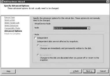
Figure 10.9 The virtual device node for the additional RDMs in a cluster node must be on a different SCSI node.
SCSI nodes for RDMs
RDMs used for shared storage in a Microsoft server cluster must be configured on a SCSI node that is different from the SCSI to which the hard disk is connected that holds the operating system. For example, if the operating system's virtual hard drive is configured to use the SCSI0 node, then the RDM should use the SCSI1 node.
9. Click the Finish button.
10. Right-click the virtual machine and select the Edit Settings option.
11. Select the new SCSI controller that was added as a result of adding the RDMs on a separate SCSI controller.
12. Select the Virtual radio button option under the SCSI Bus Sharing options, as shown in Figure 10.10.
13. Repeat steps 2 through 9 to configure additional RDMs for shared storage locations needed by nodes of a Microsoft server cluster.
14. Configure the virtual machine with two network adapters. Connect one network adapter to the production network and connect the other network adapter to the network used for heartbeat communications between nodes. Figure 10.11 shows a cluster node with two network adapters configured.
NICs in a Cluster
Because of PCI addressing issues, all RDMs should be added prior to configuring the additional network adapters. If the NICs are configured first, you may be required to revisit the network adapter configuration after the RDMs are added to the cluster node.
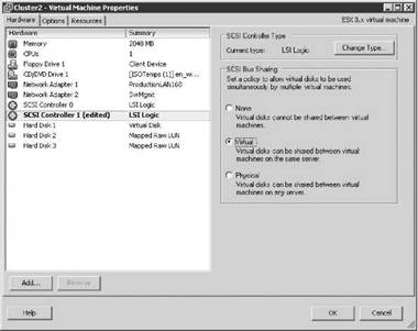
Figure 10.10 The SCSI bus sharing for the new SCSI adapter must be set to Virtual to support running a virtual machine as a node in a Microsoft server cluster.
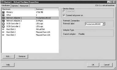
Figure 10.11 A node in a Microsoft server cluster requires at least two network adapters. One adapter must be able to communicate on the production network, and the second adapter is configured for internal cluster heartbeat communication.
15. Power on the first node of the cluster, and assign valid IP addresses to the network adapters configured for the production and heartbeat networks. Then format the additional drives and assign drive letters, as shown in Figure 10.12.
16. Shut down the first cluster node.
17. In the VirtualCenter inventory, select the ESX Server host where the first cluster node is configured and then select the Configuration tab.
18. Select Advanced Settings from the Software menu.
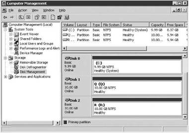
Figure 10.12 The RDMs presented to the first cluster node are formatted and assigned drive letters.
19. In the Advanced Settings dialog box, configure the following options, as shown in Figure 10.13:
? Set the Disk.ResetOnFailure option to 1.
? Set the Disk.UseLunReset option to 1.
? Set the Disk.UseDeviceReset option to 0.
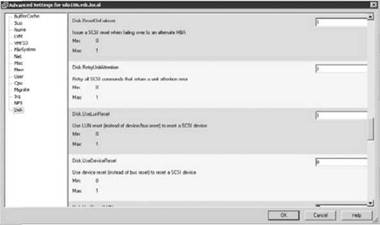
Figure 10.13 ESX Server hosts with virtual machines configured as cluster nodes require changes to be made to several advanced disk configuration settings.
20. Proceed to the next section to configure the second cluster node and the respective ESX Server host.
Creating the Second Cluster Node
To create the second cluster node, follow these steps:
1. Create a second virtual machine that is a member of the same Active Directory domain as the first cluster node.
2. Add the same RDMs to the second cluster node using the same SCSI node values. For example, if the first node used SCSI 1:0 for the first RDM and SCSI 1:1 for the second RDM, then configure the second node to use the same configuration. As in the first cluster node configuration, add all RDMs to the virtual machine before moving on to step 3 to configure the network adapters. Don't forget to edit the SCSI bus sharing configuration for the new SCSI adapter.
3. Configure the second node with an identical network adapter configuration.
4. Verify that the hard drives corresponding to the RDMs can be seen in Disk Manager. At this point the drives will show as a status of Healthy but drive letters will not be assigned.
5. Power off the second node.
6. Edit the advanced disk settings for the ESX Server host with the second cluster node.
Creating the Management Cluster
To create the management cluster, follow these steps:
1. If you have the authority, create a new user account that belongs to the same Windows Active Directory domain as the two cluster nodes. The account does not need to be granted any special group memberships at this time.
2. Power on the first node of the cluster and log in as a user with administrative credentials.
3. Click Start?Programs?Administrative Tools, and select the Cluster Administrator console.
4. Select the Create new cluster option from the Open Connection to Cluster dialog box, as shown in Figure 10.14. Click OK.
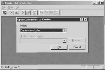
Figure 10.14 The first cluster created is used to manage the nodes of the cluster.
5. Provide a unique name for the name of the cluster, as shown in Figure 10.15. Ensure that it does not match the name of any existing computers on the network.
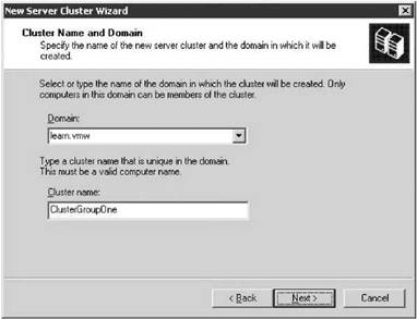
Figure 10.15 Configuring a Microsoft server cluster is heavily based on domain membership and the cluster name. The name provided to the cluster must be unique within the domain to which it belongs.
6. As shown in Figure 10.16, the next step is to execute the cluster feasibility analysis to check for all cluster-capable resources. Then click Next.
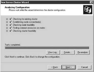
Figure 10.16 The cluster analysis portion of the cluster configuration wizard identifies that all cluster-capable resources are available.
7. Provide an IP address for cluster management. As shown in Figure 10.17, the IP address configured for cluster management should be an IP address that is accessible from the network adapters configured on the production network. Click Next.
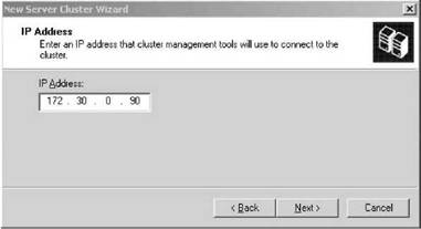
Figure 10.17 The IP address provided for cluster management should be unique and accessible from the production network.
Cluster Management
To access and manage a Microsoft cluster, create a Host (A) record in the zone that corresponds to the domain to which the cluster nodes belong.
8. Provide the account information for the cluster service user account created in step 1 of the “Creating the Management Cluster” section. Note that the Cluster Service Account page of the New Server Cluster Wizard, shown in Figure 10.18, acknowledges that the account specified will be granted membership in the local administrators group on each cluster node. Therefore, do not share the cluster service password with users who should not have administrative capabilities. Click Next.
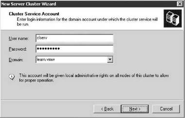
Figure 10.18 The cluster service account must be a domain account and will be granted local administrator rights on each cluster node.
9. At the completion of creating the cluster timeline, shown in Figure 10.19, click Next.
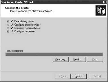
Figure 10.19 The cluster installation timeline provides a running report of the items configured as part of the installation process.
10. Continue to review the Cluster Administrator snap-in and review the new management cluster that was created, shown in Figure 10.20.
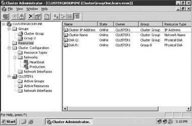
Figure 10.20 The completion of the initial cluster management creation wizard will result in a Cluster Group and all associated cluster resources.
Adding the Second Node to the Management Cluster
To add the second node to the management cluster, follow these steps:
1. Leave the first node powered on and power on the second node.
2. Right-click the name of the cluster, select the New option, and then click the Node option, as shown in Figure 10.21.
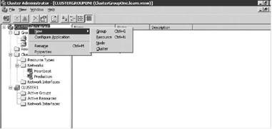
Figure 10.21 Once the management cluster is complete, an additional node can be added.
3. Specify the name of the node to be added to the cluster and then click Next, as shown in Figure 10.22.
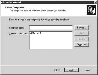
Figure 10.22 You can type the name of the second node into the text box or find it using the Browse button.
4. Once the cluster feasibility check has completed (see Figure 10.23), click the Next button.
Feasibility Stall
If the feasibility check stalls and reports a 0x00138f error stating that a cluster resource cannot be found, the installation will continue to run. This is a known issue with the Windows Server 2003 cluster configuration. If you allow the installation to continue, it will eventually complete and function as expected. For more information visit http://support.microsoft.com/kb/909968.
5. Proceed to review the Cluster Administrator identifying that two nodes now exist within the new cluster.
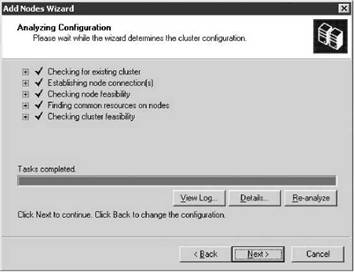
Figure 10.23 A feasibility check is executed against each potential node to validate the hardware configuration that supports the appropriate shared resources and network configuration parameters.
At this point the management cluster is complete; from here, application and service clusters can be configured. Some applications like Microsoft SQL Server 2005 and Microsoft Exchange Server 2007 are not only cluster-aware applications but also allow for the creation of a server cluster as part of the standard installation wizard. Other cluster-aware applications and services can be configured into a cluster using the cluster administrator.
