Êíèãà: Introduction to Microprocessors and Microcontrollers
A modification to the program
A modification to the program
In the last program we controlled the voltages to each of the PortB outputs. With slight modifications we would be able to apply any combinations of voltages to control any external circuits. Even this first circuit has significant control capabilities but now we are going to extend the capability by applying a counting sequence to the output signals.
All programs are built on the backs of other programs that we have used before so we can save considerable time by keeping copies of our successful programs to be recycled whenever possible. This is well demonstrated in this example.
The program consists of three steps, two of which we have already designed and tested, so we know it works. If the new program refuses to work, we don’t have to start from scratch, we know two–thirds of it is OK. This is a very powerful method of designing programs and whole libraries of programs are available so new developments can be reduced to slotting together ready-made program segments.
When we make changes to a previously program, it is important to save the new version under a new name so that, in the event of a disaster, we can retreat and start again.
Here is the section that we have ‘borrowed’ from our previous work:
     ORG 000

     BSF 3,5

     CLRW

     MOVWF 86; PortB data direction = output

     BCF 3,5

     MOVLW 55

     MOVWF 06; PortB data set to a start value
At this stage we can, of course, set the start value for the output to any value between 00H to FFH which is binary B’00000000’ to B’11111111’.
We have only one new instruction to worry about: INCF f,d. It increments or increases the value of a selected file ‘f’ by 1, and where the new value goes to is determined by the value of the ‘d’ term. If ‘d’ is 0 the new value is put into the W register but if it is 1, the new value is put back into the register in use.
PortB data register is register 06 so the code INCF 06,1 will take the current value of PortB data, increase it by 1 and put the answer back into PortB data so our starting value of 55 will change to 56 and the output voltages on the pins will change from 01010101 to 01010110.
This was just a single count, but for a continuous count we could use a label to make the program jump back and do the INCF trick again and again. When it reaches its maximum value, it will roll over to zero and start again so the count process can be continuous. Our program would now be:
      ORG 000

      BSF 3,5

      CLRW

      MOVWF 86  ; PortB data direction = output

      BCF 3,5

      MOVLW 55

      MOVWF 06  ; PortB data set to a start value

again INCF 06,1

      goto again; go back and INCF again

      end       ; end of source code
One more step
The speed at which the count continues is determined by the rate at which instructions are being followed.
Slowing things down
If we wish to slow things down, we can give the microcontroller something to do just to keep it busy. We have a NOP instruction which does absolutely nothing but takes one instruction cycle to do it. Since it doesn’t do anything, it doesn’t matter how many we include in a program, or where we use them. For a significant delay we made need hundreds, which is not an elegant way of solving a problem.
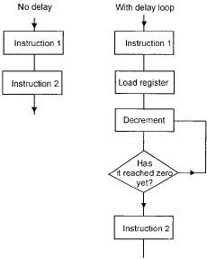
In the last modification to the problem, we made it count up on the PortB register. Now this takes time, so we could use this counting trick as a time waster. The PIC has 68 general purpose registers that can be made to count for us. Just choose any one of them and have it count for a set number of counts and then we can go back and count once on the PortB register, then go back to the time waste count. In Figure 16.4, we have loaded a register with a number, say 30H (48 in decimal). The next instruction decreases it by 1 to give 2FH (not 29!!!) and since the answer is not zero, we go around the loop and decrement it again to 2EH and so on until it gets to zero whereupon it leaves the loop to carry out ‘instruction 2’ shown in the figure.

Figure 16.4 Using a timing loop
The instruction we are going to use this time is INCFSZ f,d. This is designed just for this type of counting job. It decrements the chosen register and if d=0, the result goes into the W register but if it is 1, it will go back into the same register. For our purposes we would load the code as DECFSZ 20,1. This would decrement register 20 and put the answer back into register 20. When this register reaches zero, it will miss out the next instruction to stop it going around the loop again and will move on to the next instruction.
A slower count
Once again, this uses some of our previous programs.
      ORG 000

      BSF 3,5

      CLRW

      MOVWF 86   ; PortB data direction = output

      BCF 3,5

      MOVLW 55   ; PortB data set to a start value

      MOVWF 06

again INCF 06,1

      MOVLW 30   ; Loads W with 30H

      MOVWF 20   ; puts the number 30 into file 20

count DECFSZ 20,1; decrements register 20

      goto count ; keeps decrements until it gets to zero

      goto again ; returns to increment PortB

      end
For the slowest count on PortB, we would have to increase the count number in register 20 to its maximum number which, using this microcontroller is 7FH or 127 in decimal.
Calculating the delay
Starting from the moment that PortB is incremented:
MOVLW takes 1 count.
MOVWF takes 1 count.
DECFSZ takes 1 count normally but 2 when it leaves the loop.
As the register was loaded with the hex number 30, which is 48 in decimal, it will go around the ‘count’ loop 47 times at 1 instruction clock each and 2 clocks as it leaves the loop. This gives a total of 49 cycles.
goto will be used 48 times at 2 clocks each giving a total of 96 clocks.
goto will also be used once to return to the PortB, this is another 2 cycles.
Finally, INCF takes 1 count to increment the value on PortB.
The total is: 1 + 1 + 49 + 48 + 2 + 1 = 102 cycles
Assuming a crystal frequency of 32 kHz, we can divide it by 4 to give the instruction clock frequency and then by the delay of 102 cycles to give the rate at which the PortB is incremented of about 78 counts per second. PortB counts in binary from 0000 0000 to 1111 1111 and will finish its count after 256 counts so it will start recounting after 256/78 or roughly 3.3 seconds. We could reasonably double this time delay by a liberal sprinkling of NOPs or using a longer loop.
Longer delays
We have three alternatives.
1 For small changes, we could add some NOPs inside of the counting loop to boost the number of counts.
2 Our delay was built into the main program but we could have used it as a subroutine. A subroutine is any block of code that we may want to use more than once. In the main program we insert an instruction CALL followed by a label to identify the block of code so for our delay loop which we called ‘count’ we would insert the instruction ‘CALL count’ at any time we want to use our program to cause a delay. When the delay loop ‘count’ has been completed, we insert the instruction RETURN at the end of this block of code and the microcontroller will return to the main program.
The benefit of using a subroutine is that we can run the ‘count’ delay twice just by inserting the instruction CALL count twice in the main program and we don’t have to enter the delay loop again with the fear that we will mistype something and it will all collapse. We can make a subroutine as long as we want and use it as often as we want just by adding the CALL and RETURN instructions.
Here is our previous program but reorganized to use the delay loop ‘count’ as a subroutine.
count DECFSZ 20,1; decrements register 20

      goto count ; keeps decrements until it gets to zero

      RETURN

      ORG 000

      BSF 3,5

      CLRW

      MOVWF 86  ; PortB data direction = output

      BCF 3,5

      MOVLW 55

      MOVWF 06  ; PortB data set to a start value

again INCF 06,1

      MOVLW 30  ; Loads W with 30H

      MOVWF 20  ; puts the number 30 into file 20

      CALL count

      goto again; returns to increment PortB

      end
The subroutine is called count and has the instruction RETURN at the end.
The main program has the instruction CALL count which means ‘go and get a subroutine and use the one called count’. We can then put:
CALL count

CALL count

CALL count
In the main program which would be an easy way to treble the length of a delay. We could design a subroutine called ‘1second’ and another for ‘0.1second’.
Then if we needed to insert a delay of 2.3 seconds, we could just add:
CALL 1second

CALL 1second

CALL 0.1second

CALL 0.1second

CALL 0.1second
All subroutines would end with the same code RETURN, so how do they know where they have to go back to?
The answer is a series of memory locations called a stack. Each return address is stored in the stack in order that each CALL occurs, the relevant address is sent to the stack and as each RETURN will occur in sequence, the addresses will be unloaded from the stack in the order required. This is a first-in last-out (FILO) organization. See Chapter 8 for more on the stack.
A subroutine can include a CALL to another subroutine. These are called nested subroutines – the PIC16F84A has room in its stack for eight return addresses – which is pretty small by microprocessor standards.
3 In the PIC, most instructions are completed in a single instruction cycle which is 14 of the clock speed. To change the delay, we could always change the clock speed. There are two benefits, a slower clock speed reduces the power consumed, there is no low-speed limit for the PIC, unlike some devices. Generally subroutines are preferred as there are often other constraints on the clock speed.
- Appendix I. GNU General Public License
- 0. Preamble
- 1. TERMS AND CONDITIONS FOR COPYING, DISTRIBUTION AND MODIFICATION
- Preamble
- Terms and Conditions for Copying, Distribution and Modification
- No Warranty
- 9.1.6. The UNIX Subsystem
- Peter Naur, Programming as Theory Building
- 12. They Called It LISP for a Reason: List Processing
- 0. PREAMBLE
- 6.8.1 Pausing a Macro for Keyboard Input
- 4. COMMERCIAL DISTRIBUTION


