Книга: DirectX 8 Programming Tutorial
Texture Mapping
Texture Mapping
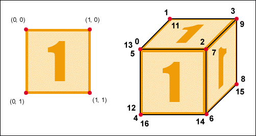
Now that we know about texture coordinates, we can apply our texture to an object in our scene, this is called Texture Mapping. The process of texture mapping is to map texture coordinates to vertices in a scene, therefore each vertex will have two extra values, U and V. Fig 6.2 below, shows an example of mapping a texture on to a cube. The example uses one texture placed on each side of a cube. The cubes vertices have been numbered in the same way as our cube structure in http://www.andypike.com/tutorials/directx8/003.htm and our code for this tutorial.
Therefore, the texture coordinates for each vertex are as follows (where vertex number = (U, V)):
0 = (0, 1) 9 = (0, 0)
1 = (0, 0) 10 = (1, 1)
2 = (1, 1) 11 = (1, 0)
3 = (1, 0) 12 = (0, 1)
4 = (0, 1) 13 = (0, 0)
5 = (0, 0) 14 = (0, 1)
6 = (1, 1) 15 = (0, 0)
7 = (1, 0) 16 = (1, 1)
8 = (0, 1) 17 = (1, 0)

Fig 6.2
- Texture Size
- DirectX Tutorial 6: Textures
- What is a Texture?
- Texture Coordinates
- SERVER CLIENT MAPPING
- 10.3.3. Mapping Driver
- Mapping a network drive
- 2.4 Mapping Executable Images into Target Embedded Systems
- 2.4.2 Mapping Executable Images
- 12.3.2 Mapping Generic Functions to Driver Functions
- Shared Interrupt Mappings
- DirectX Tutorial 9: Textured Spheres, Cylinders and Cones


