Книга: Real-Time Concepts for Embedded Systems
2.4.1 Linker Command File
2.4.1 Linker Command File
The format of the linker command file, as well as the linker directives, vary from linker to linker. It is best to consult the programmer’s reference manual from the vendor for specific linker commands, syntaxes, and extensions. Some common directives, however, are found among the majority of the available linkers used for building embedded applications. Two of the more common directives supported by most linkers are MEMORY and SECTION.
The MEMORY directive can be used to describe the target system’s memory map. The memory map lists the different types of memory (such as RAM, ROM, and flash) that are present on the target system, along with the ranges of addresses that can be accessed for storing and running an executable image. An embedded developer needs to be familiar with the addressable physical memory on a target system before creating a linker command file. One of the best ways to do this process, other than having direct access to the hardware engineering team that built the target system, is to look at the target system’s schematics, as shown in Figure 2.5, and the hardware documentation. Typically, the hardware documentation describes the target system’s memory map.

Figure 2.5: Simplified schematic and memory map for a target system.
The linker combines input sections having the same name into a single output section with that name by default. The developer-created, custom-named sections appear in the object file as independent sections. Sometimes developers might want to change this default linker behavior of only coalescing sections with the same name. The embedded developer might also need to instruct the linker on where to map the sections, in other words, what addresses should the linker use when performing symbol resolutions. The embedded developer can use the SECTION directive to achieve these goals.
The MEMORY directive defines the types of physical memory present on the target system and the address range occupied by each physical memory block, as specified in the following generalized syntax
MEMORY {

 area-name: org = start-address, len = number-of-bytes

 …

}
In the example shown in Figure 2.5, three physical blocks of memory are present:
· a ROM chip mapped to address space location 0, with 32 bytes,
· some flash memory mapped to address space location 0x40, with 4,096 bytes, and
· a block of RAM that starts at origin 0x10000, with 65,536 bytes.
Translating this memory map into the MEMORY directive is shown in Listing 2.2. The named areas are ROM, FLASH, and RAM.
Listing 2.2: Memory map.

MEMORY {

 ROM: origin = 0x0000h, length = 0x0020h

 FLASH: origin = 0x0040h, length = 0x1000h

 RAM: origin = 0x1000h, length = 0x10000h

}
The SECTION directive tells the linker which input sections are to be combined into which output section, which output sections are to be grouped together and allocated in contiguous memory, and where to place each section, as well as other information. A general notation of the SECTION command is shown in Listing 2.3.
Listing 2.3: SECTION command.
SECTION {

 output-section-name: {contents} › area-name

 …

 GROUP {

  [ALIGN(expression)]

  section-definition

  …

 } › area-name

}
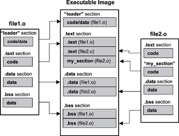
The example shown in Figure 2.6 contains three default sections (.text,.data, and.bss), as well as two developer-specified sections (loader and my_section), contained in two object files generated by a compiler or assembler (file1.o and file2.o). Translating this example into the MEMORY directive is shown in Listing 2.4.

Figure 2.6: Combining input sections into an executable image.
Listing 2.4: Example code.
SECTION {

 .text:

 {

  my_section

  *(.text)

 }

 loader: › FLASH

 GROUP ALIGN (4):

 {

  .text,

  .data: {}

  .bss: {}

 } ›RAM

}
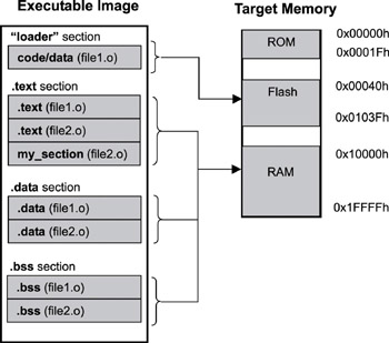
The SECTION command in the linker command file instructs the linker to combine the input section named my_section and the default.text sections from all object files into the final output.text section. The loader section is placed into flash memory. The sections.text,.data, and.bss are grouped together and allocated in contiguous physical RAM memory aligned on the 4-byte boundary, as shown in Figure 2.7.

Figure 2.7: Mapping an executable image into the target system.
Tips on section allocation include the following:
· allocate sections according to size to fully use available memory, and
· examine the nature of the underlying physical memory, the attributes, and the purpose of a section to determine which physical memory is best suited for allocation.
- Shared Cache file
- Безопасность внешних таблиц. Параметр EXTERNAL FILE DIRECTORY
- Chapter 13. rc.firewall file
- Appendix A. Detailed explanations of special commands
- Basics of the iptables command
- Commands
- Creating CDs from the Command Line
- 4.3.3. Makefile Targets
- Using the kill Command to Control Processes
- The echo command
- Что это за файл – pagefile.sys?
- Для чего нужны папки Windows, Documents and Settings, Program Files и Temp?


