Книга: Distributed operating systems
6.2.4. Switched Multiprocessors
Разделы на этой странице:
6.2.4. Switched Multiprocessors
Although bus-based multiprocessors and ring-based multiprocessors work fine for small systems (up to around 64 CPUs), they do not scale well to systems with hundreds or thousands of CPUs. As CPUs are added, at some point the bus or ring bandwidth saturates. Adding additional CPUs does not improve the system performance.
Two approaches can be taken to attack the problem of not enough bandwidth:
1. Reduce the amount of communication.
2. Increase the communication capacity.
We have already seen an example of an attempt to reduce the amount of communication by using caching. Additional work in this area might center on improving the caching protocol, optimizing the block size, reorganizing the program to increase locality of memory references, and so on.
Nevertheless, eventually there comes a time when every trick in the book has been used, but the insatiable designers still want to add more CPUs and there is no bus bandwidth left. The only way out is to add more bus bandwidth. One approach is to change the topology, going, for example, from one bus to two buses or to a tree or grid. By changing the topology of the interconnection network, it is possible to add additional communication capacity.
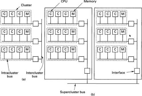
A different method is to build the system as a hierarchy. Continue to put some number of CPUs on a single bus, but now regard this entire unit (CPUs plus bus) as a cluster. Build the system as multiple clusters and connect the clusters using an intercluster bus, as shown in Fig. 6-6(a). As long as most CPUs communicate primarily within their own cluster, there will be relatively little intercluster traffic. If one intercluster bus proves to be inadequate, add a second intercluster bus, or arrange the clusters in a tree or grid. If still more bandwidth is needed, collect a bus, tree, or grid of clusters together into a super-cluster, and break the system into multiple superclusters. The superclusters can be connected by a bus, tree, or grid, and so on. Fig. 6-6(b) shows a system with three levels of buses.

Fig. 6-6. (a) Three clusters connected by an intercluster bus to form one supercluster. (b) Two superclusters connected by a supercluster bus.
In this section we will look at a hierarchical design based on a grid of clusters. The machine, called Dash, was built as a research project at stanford university (Lenoski et al., 1992). Although many other researchers are doing similar work, this one is a typical example. In the remainder of this section we with focus on the 64-CPU prototype that was actually constructed, but the design principles have been chosen carefully so that one could equally well build a much larger version. The description given below has been simplified slightly in a few places to avoid going into unnecessary detail.
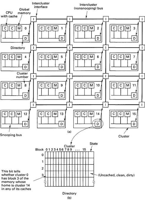
A simplified diagram of the Dash prototype is presented in Fig. 6-7(a). It consists of 16 clusters, each cluster containing a bus, four CPUs, 16M of the global memory, and some I/O equipment (disks, etc.). To avoid clutter in the figure, the I/O equipment and two of the CPUs have been omitted from each cluster. Each CPU is able to snoop on its local bus, as in Fig. 6-2(b), but not on other buses.
The total address space available in the prototype is 256M, divided up into 16 regions of 16M each. The global memory of cluster 0 holds addresses 0 to 16M. The global memory of cluster 1 holds addresses 16M to 32M, and so on. Memory is cached and transferred in units of 16-byte blocks, so each cluster has 1M memory blocks within its address space.
Directories
Each cluster has a directory that keeps track of which clusters currently have copies of its blocks. Since each cluster owns 1M memory blocks, it has 1M entries in its directory, one per block. Each entry holds a bit map with one bit per cluster telling whether or not that cluster has the block currently cached. The entry also has a 2-bit field telling the state of the block. The directories are essential to the operation of Dash, as we shall see. In fact, the name Dash comes from "Directory Architecture for Shared memory."
Having 1M entries of 18 bits each means that the total size of each directory is over 2M bytes. With 16 clusters, the total directory memory is just over 36M, or about 14 percent of the 256M. If the number of CPUs per cluster is increased, the amount of directory memory is not changed. Thus having more CPUs per cluster allows the directory cost to be amortized over a larger number of CPUs, reducing the cost per CPU. Also, the cost of the directory and bus controllers per CPU are reduced. In theory, the design works fine with one CPU per cluster, but the cost of the directory and bus hardware per CPU then becomes larger.
A bit map is not the only way to keep track of which cluster holds which cache block. An alternative approach is to organize each directory entry as an explicit list telling which clusters hold the corresponding cache block. If there is little sharing, the list approach will require fewer bits, but if there is substantial sharing, it will require more bits. Lists also have the disadvantage of being variable-length data structures, but these problems can be solved. The M.I.T. Alewife multiprocessor (Agarwal et al., 1991; and Kranz et al., 1993), for example, is similar to Dash in many respects, although it uses lists instead of bit maps in its directories and handles directory overflows in software.

Fig. 6-7. (a) A simplified view of the Dash architecture. Each cluster actually has four CPUs, but only two are shown here. (b) A Dash directory.
Each cluster in Dash is connected to an interface that allows the cluster to communicate with other clusters. The interfaces are connected by intercluster links (primitive buses) in a rectangular grid, as shown in Fig. 6-7(a). As more clusters are added to the system, more intercluster links are added, too, so the bandwidth increases and the system scales. The intercluster link system uses wormhole routing, which means that the first part of a packet can be forwarded even before the entire packet has been received, thus reducing the delay at each hop. Although not shown in the figure, there are actually two sets of intercluster links, one for request packets and one for reply packets. The intercluster links cannot be snooped upon.
Caching
Caching is done on two levels: a first-level cache and a larger second-level cache. The first-level cache is a subset of the second-level cache, so only the latter will concern us here. Each (second-level) cache monitors the local bus using a protocol somewhat similar to the cache ownership protocol of Fig. 6-4.
Each cache block can be in one of the following three states:
1. UNCACHED — The only copy of the block is in this memory.
2. CLEAN — Memory is up-to-date; the block may be in several caches.
3. DIRTY — Memory is incorrect; only one cache holds the block.
The state of each cache block is stored in the State field of its directory entry, as shown in Fig. 6-7(b).
Protocols
The Dash protocols are based on ownership and invalidation. At every instant, each cache block has a unique owner. For UNCACHED or CLEAN blocks, the block's home cluster is the owner. For dirty blocks, the cluster holding the one and only copy is the owner. Writing on a CLEAN block requires first finding and invalidating all existing copies. This is where the directories come in.
To see how this mechanism works, let us first consider how a CPU reads a memory word. It first checks its own caches. If neither cache has the word, a request is issued on the local cluster bus to see if another CPU in the cluster has the block containing it. If one does, a cache-to-cache transfer of the block is executed to place the block in the requesting CPU's cache. If the block is CLEAN, a copy is made; if it is DIRTY, the home directory is informed that the block is now CLEAN and shared. Either way, a hit from one of the caches satisfies the instruction but does not affect any directory's bit map.
If the block is not present in any of the cluster's caches, a request packet is sent to the block's home cluster, which can be determined by examining the upper 4 bits of the memory address. The home cluster might well be the requester's cluster, in which case the message is not sent physically. The directory management hardware at the home cluster examines its tables to see what state the block is in. If it is UNCACHED or CLEAN, the hardware fetches the block from its global memory and sends it back to the requesting cluster. It then updates its directory, marking the block as cached in the requester's cluster (if it was not already so marked).
If, however, the needed block is DIRTY, the directory hardware looks up the identity of the cluster holding the block and forwards the request there. The cluster holding the dirty block then sends it to the requesting cluster and marks its own copy as CLEAN because it is now shared. It also sends a copy back to the home cluster so that memory can be updated and the block state changed to CLEAN. All these cases are summarized in Fig. 6-8(a). Where a block is marked as being in a new state, it is the home directory that is changed, as it is the home directory that keeps track of the state.
Writes work differently. Before a write can be done, the CPU doing the write must be sure that it is the owner of the only copy of the cache block in the system. If it already has the block in its on-board cache and the block is dirty, the write can proceed immediately. If it has the block but it is clean, a packet is first sent to the home cluster requesting that all other copies be tracked down and invalidated.
If the requesting CPU does not have the cache block, it issues a request on the local bus to see if any of the neighbors have it. If so, a cache-to-cache (or memory-to-cache) transfer is done. If the block is CLEAN, all other copies, if any, must be invalidated by the home cluster.
If the local broadcast fails to turn up a copy and the block is homed elsewhere, a packet is sent to the home cluster. Three cases can be distinguished here. If the block is UNCACHED, it is marked dirty and sent to the requester. If it is CLEAN, all copies are invalidated and then the procedure for UNCACHED is followed. If it is DIRTY, the request is forwarded to the remote cluster currently owning the block (if needed). This cluster invalidates its own copy and satisfies the request. The various cases are shown in Fig. 6-8(b).
| Location where the block was found | ||||
|---|---|---|---|---|
| Block state | R's cache | Neighbor's cache | Home cluster's memory | Some cluster's cache |
| UNCACHED | Send block to R; mark as CLEAN and cached only in R's cluster | |||
| CLEAN | Use block | Copy block to R's cache | Copy block from memory to R; mark as also cached in R's cluster | |
| DIRTY | Use block | Send block to R and to home cluster; tell home to mark it as CLEAN and cached in R's cluster | Send block to R and to home cluster (if cached elsewhere}; tell home to mark it as CLEAN and also cached in R's cluster | |
(a)
| Location where the block was found | ||||
|---|---|---|---|---|
| Block state | R's cache | Neighbor's cache | Home cluster's memory | Some cluster's cache |
| UNCACHED | Send block to R; mark as DIRTY and cached only in R's cluster | |||
| CLEAN | Send message to home asking for exclusive ownership in DIRTY state; if granted, use block | Copy and invalidate block; send message to home asking for exclusive ownership in DIRTY state | Send block to R; invalidate all cached copies; mark it as DIRTY and cached only in R's cluster | |
| DIRTY | Use block | Cache-to-cache transfer to R; invalidate neighbor's copy | Send block directly to R; invalidate cached copy; home marks it as DIRTY and cached only in R's cluster | |
Fig. 6-8. Dash protocols. The columns show where the block was found. The rows show the state it was in. The contents of the boxes show the action taken. R refers to the requesting CPU. An empty box indicates an impossible situation. (a) Reads. (b) Writes.
Obviously, maintaining memory consistency in Dash (or any large multiprocessor) is nothing at all like the simple model of Fig. 6-1(b). A single memory access may require a substantial number of packets to be sent. Furthermore, to keep memory consistent, the access usually cannot be completed until all the packets have been acknowledged, which can have a serious effect on performance. To get around these problems, Dash uses a variety of special techniques, such as two sets of intercluster links, pipelined writes, and different memory semantics than one might expect. We will discuss some of these issues later. For the time being, the bottom line is that this implementation of "shared memory" requires a large data base (the directories), a considerable amount of computing power (the directory management hardware), and a potentially large number of packets that must be sent and acknowledged. We will see later that implementing distributed shared memory has precisely the same properties. The difference between the two lies much more in the implementation technique than in the ideas, architecture, or algorithms.


