Книга: Advanced PIC Microcontroller Projects in C
Project Hardware
Project Hardware
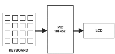
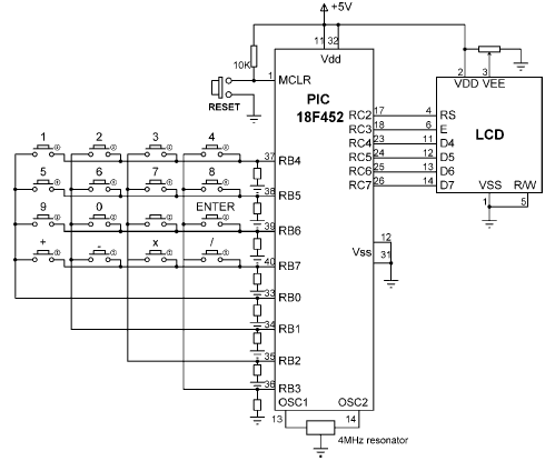
The block diagram of the project is shown in Figure 6.45. The circuit diagram is given in Figure 6.46. A PIC18F452 microcontroller with a 4MHz resonator is used in the project. Columns of the keypad are connected to port pins RB0–RB3 and rows are connected to port pins RB4–RB7 via pull-down resistors. The LCD is connected to PORTC in default mode, as in Figure 6.39. An external reset button is also provided to reset the microcontroller should it be necessary.

Figure 6.45: Block diagram of the project

Figure 6.46: Circuit diagram of the project
Оглавление статьи/книги


