Книга: Advanced PIC Microcontroller Projects in C
PROJECT 6.9 — Calculator with Keypad and LCD
Project Description
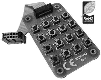
Keypads are small keyboards used to enter numeric or alphanumeric data into microcontroller systems. Keypads are available in a variety of sizes and styles, from 2?2 to 4?4 or even bigger.
This project uses a 4?4 keypad (shown in Figure 6.43) and an LCD to design a simple calculator.

Figure 6.43: 4?4 keypad
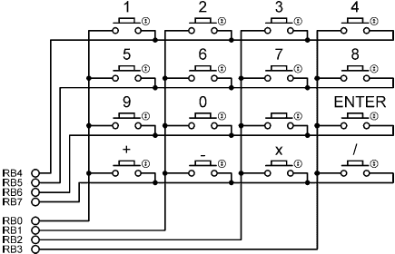
Figure 6.44 shows the structure of the keypad used in this project which consists of sixteen switches formed in a 4?4 array and named numerals 0–9, Enter, “+”, “.”, “–”, “*”, and “/”. Rows and columns of the keypad are connected to PORTB of a microcontroller which scans the keypad to detect when a switch is pressed. The operation of the keypad is as follows:
• A logic 1 is applied to the first column via RB0.
• Port pins RB4 to RB7 are read. If the data is nonzero, a switch is pressed. If RB4 is 1, key 1 is pressed, if RB5 is 1, key 4 is pressed, if RB6 is 1, key 9 is pressed, and so on.
• A logic 1 is applied to the second column via RB1.
• Again, port pins RB4 to RB7 are read. If the data is nonzero, a switch is pressed. If RB4 is 1, key 2 is pressed, if RB5 is 1, key 6 is pressed, if RB6 is 1, key 0 is pressed, and so on.
• This process is repeated for all four columns continuously.

Figure 6.44: 4?4 keypad structure
In this project a simple integer calculator is designed. The calculator can add, subtract, multiply, and divide integer numbers and show the result on the LCD. The operation of the calculator is as follows: When power is applied to the system, the LCD displays text “CALCULATOR” for 2 seconds. Then text “No1:” is displayed in the first row of the LCD and the user is expected to type the first number and then press the ENTER key. Then text “No2:” is displayed in the second row of the LCD, where the user enters the second number and presses the ENTER key. After this, the appropriate operation key should be pressed. The result is displayed on the LCD for five seconds and then the LCD is cleared, ready for the next calculation. The example that follows shows how numbers 12 and 20 can be added:
No1: 12 ENTER

No2: 20 ENTER

Op: +

Res = 32
In this project the keyboard is labeled as follows:
1 2 3 4

5 6 7 8

9 0   ENTER

+ - X /
One of the keys, between 0 and ENTER, is not used in this project.
- Разработка приложений баз данных InterBase на Borland Delphi
- Open Source Insight and Discussion
- Introduction to Microprocessors and Microcontrollers
- Chapter 6. Traversing of tables and chains
- Chapter 8. Saving and restoring large rule-sets
- Chapter 11. Iptables targets and jumps
- Chapter 5 Installing and Configuring VirtualCenter 2.0
- Chapter 16. Commercial products based on Linux, iptables and netfilter
- Appendix A. Detailed explanations of special commands
- Appendix B. Common problems and questions
- Appendix E. Other resources and links
- Project PDL


