Книга: Advanced PIC Microcontroller Projects in C
Project Description
Project Description
This project describes the design of a 7-segment LED-based counter which counts from 0 to 9 continuously with a one-second delay between counts. The project shows how a 7-segment LED can be interfaced and used in a PIC microcontroller project.
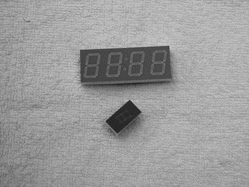
7-segment displays are used frequently in electronic circuits to show numeric or alphanumeric values. As shown in Figure 6.20, a 7-segment display consists basically of 7 LEDs connected such that the numbers from 0 to 9 and some letters can be displayed. Segments are identified by the letters from a to g, and Figure 6.21 shows the segment names of a typical 7-segment display.

Figure 6.20: Some 7-segment displays

Figure 6.21: Segment names of a 7-segment display
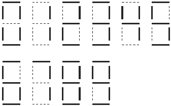
Figure 6.22 shows how the numbers from 0 to 9 are obtained by turning ON different segments of the display.

Figure 6.22: Displaying numbers 0 to 9
7-segment displays are available in two different configurations: common cathode and common anode. As shown in Figure 6.23, in common cathode configuration, all the cathodes of all segment LEDs are connected together to the ground. The segments are turned ON by applying a logic 1 to the required segment LED via current limiting resistors. In common cathode configuration the 7-segment LED is connected to the microcontroller in current sourcing mode.

Figure 6.23: Common cathode configuration
In common anode configuration, the anode terminals of all the LEDs are connected together as shown in Figure 6.24. This common point is then normally connected to the supply voltage. A segment is turned ON by connecting its cathode terminal to logic 0 via a current limiting resistor. In common anode configuration the 7-segment LED is connected to the microcontroller in current sinking mode.

Figure 6.24: Common anode configuration
In this project, a Kingbright SA52-11 red common anode 7-segment display is used. This is a 13mm (0.52 inch) display with ten pins that includes a segment LED for the decimal point. Table 6.7 shows the pin configuration of this display.
Table 6.7: SA52-11 pin configuration
| Pin | number Segment |
|---|---|
| 1 | e |
| 2 | d |
| 3 | common anode |
| 4 | c |
| 5 | decimal point |
| 6 | b |
| 7 | a |
| 8 | common anode |
| 9 | f |
| 10 | g |


