Книга: Advanced PIC Microcontroller Projects in C
5.2.5 Breadboards
5.2.5 Breadboards
Building an electronic circuit requires connecting the components as shown in the relevant circuit diagram, usually by soldering the components together on a strip board or a printed circuit board (PCB). This approach is appropriate for circuits that have been tested and are functioning as desired, and also when the circuit is being made permanent. However, making a PCB design for just a few applications — for instance, while still developing the circuit — is not economical.
Instead, while the circuit is still under development, the components are usually assembled on a solderless breadboard. A typical breadboard (see Figure 5.24) consists of rows and columns of holes spaced so that integrated circuits and other components can be fitted inside them. The holes have spring actions so the component leads are held tightly in place. There are various types and sizes of breadboards, suitable for circuits of different complexities. Breadboards can also be stacked together to make larger boards for very complex circuits. Figure 5.25 shows the internal connection layout of the breadboard in Figure 5.24.

Figure 5.24: A typical breadboard layout

Figure 5.25: Internal wiring of the breadboard in Figure 5.24
The top and bottom halves of the breadboard are entirely separate. Columns 1 to 20 in rows A to F are connected to each other on a column basis. Rows G to L in columns 1 to 20 are likewise connected to each other on a column basis. Integrated circuits are placed such that the legs on one side are on the top half of the breadboard, and the legs on the other side are on the bottom half. The two columns on the far left of the board are usually reserved for the power and ground connections. Connections between components are usually made with stranded (or solid) wires plugged into the holes to be connected.
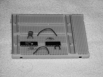
Figure 5.26 shows a breadboard holding two integrated circuits and a number of resistors and capacitors.

Figure 5.26: Picture of a breadboard with some components
The nice thing about breadboard design is that the circuit can be modified easily and quickly, and ideas can be tested without having to solder the components. Once a circuit has been tested and is working satisfactorily, the components are easily removed and the breadboard can be used for other projects.
- 5.2 Hardware Development Tools
- Советы по использованию Мастера фунций
- VMware Distributed Resource Scheduler (DRS)
- В.4. Небольшие тестовые программы
- Корпоративная книга продаж
- Глава 3. Искусство интрапренерства
- Ввод данных о предприятии
- Тема 11. Проектирование структуры организации
- Отношения с людьми


