Книга: Embedded Linux Primer: A Practical, Real-World Approach
10.3.1. Redboot Partition Table Partitioning
10.3.1. Redboot Partition Table Partitioning
One of the more common methods of defining and detecting MTD partitions stems from one of the original implementations: Redboot partitions. Redboot is a bootloader found on many embedded boards, especially ARM XScale boards such as the ADI Engineering Coyote Reference Platform.
The MTD subsystem defines a method for storing partition information on the Flash device itself, similar in concept to a partition table on a hard disk. In the case of the Redboot partitions, the developer reserves and specifies a Flash erase block that holds the partition definitions. A mapping driver is selected that calls the partition parsing functions during boot to detect the partitions on the Flash device. Figure 10-2 shows the mapping driver for our example board; it is the final highlighted entry defining CONFIG_MTD_IXP4xx.
As usual, taking a detailed look at an example helps to illustrate these concepts. We start by looking at the information provided by the Redboot bootloader for the Coyote platform. Listing 10-4 captures some of the output of the Redboot bootloader upon power-up.
Listing 10-4. Redboot Messages on Power-Up
Platform: ADI Coyote (XScale)

IDE/Parallel Port CPLD Version: 1.0

Copyright (C) 2000, 2001, 2002, Red Hat, Inc.

RAM: 0x00000000-0x04000000, 0x0001f960-0x03fd1000 available

FLASH: 0x50000000 - 0x51000000, 128 blocks of 0x00020000 bytes each.

...
This tells us that RAM on this board is physically mapped starting at address 0x00000000 and that Flash is mapped at physical address 0x50000000 through 0x51000000. We can also see that the Flash has 128 blocks of 0x00020000 (128KB) each.
Redboot contains a command to create and display partition information on the Flash. Listing 10-5 contains the output of the fis list command, part of the Flash Image System family of commands available in the Redboot bootloader.
Listing 10-5. Redboot Flash Partition List
RedBoot> fis list

Name                 FLASH addr  Mem addr    Length      Entry point

RedBoot              0x50000000  0x50000000  0x00060000  0x00000000

RedBoot config       0x50FC0000  0x50FC0000  0x00001000  0x00000000

FIS directory        0x50FE0000  0x50FE0000  0x00020000  0x00000000

RedBoot>
From Listing 10-5, we see that the Coyote board has three partitions defined on the Flash. The partition named RedBoot contains the executable Redboot bootloader image. The partition named RedBoot config contains the configuration parameters maintained by the bootloader. The final partition named FIS directory holds information about the partition table itself.
When properly configured, the Linux kernel can detect and parse this partition table and create MTD partitions representing the physical partitions on Flash. Listing 10-6 reproduces a portion of the boot messages that are output from the aforementioned ADI Engineering Coyote board, booting a Linux kernel configured with support for detecting Redboot partitions.
Listing 10-6. Detecting Redboot Partitions on Linux Boot
...

IXP4XX-Flash0: Found 1 x16 devices at 0x0 in 16-bit bank

 Intel/Sharp Extended Query Table at 0x0031

Using buffer write method

cfi_cmdset_0001: Erase suspend on write enabled

Searching for RedBoot partition table in IXP4XX-Flash0 at offset 0xfe0000

3 RedBoot partitions found on MTD device IXP4XX-Flash0

Creating 3 MTD partitions on "IXP4XX-Flash0":

0x00000000-0x00060000: "RedBoot"

0x00fc0000-0x00fc1000: "RedBoot config"

0x00fe0000-0x01000000: "FIS directory"

...
The first message in Listing 10-6 is printed when the Flash chip is detected, via the Common Flash Interface (CFI) driver, enabled via CONFIG_MTD_CFI. CFI is an industry-standard method for determining the Flash chip's characteristics, such as manufacturer, device type, total size, and erase block size. See Section 10.5.1, "Suggestions for Additional Reading," at the end of this chapter for a pointer to the CFI specification.
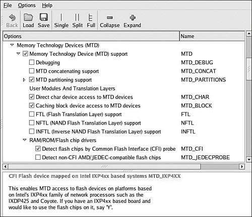
CFI is enabled via the kernel-configuration utility under the Memory Technology Devices (MTD) top-level menu. Select Detect flash chips by Common Flash Interface (CFI) probe under RAM/ROM/Flash chip drivers, as illustrated in Figure 10-3.
Figure 10-3. Kernel configuration for MTD CFI support

As shown in Listing 10-6, the Flash chip is detected via the CFI interface. Because we also enabled CONFIG_MTD_REDBOOT_PARTS (see Figure 10-2), MTD scans for the Redboot partition table on the Flash chip. Notice also that the chip has been enumerated with the device name IXP4XX-Flash0. You can see from Listing 10-6 that the Linux kernel has detected three partitions on the Flash chip, as enumerated previously using the fis list command in Redboot.
When the infrastructure is in place as described here, the Linux kernel automatically detects and creates kernel data structures representing the three Flash partitions. Evidence of these can be found in the /proc file system when the kernel has completed initialization, as shown in Listing 10-7.
Listing 10-7. Kernel MTD Flash Partitions
root@coyote:~# cat /proc/mtd

dev:    size   erasesize  name

mtd0: 00060000 00020000 "RedBoot"

mtd1: 00001000 00020000 "RedBoot config"

mtd2: 00020000 00020000 "FIS directory"

#
We can easily create a new Redboot partition. We use the Redboot FIS commands for this example, but we do not detail the Redboot commands in this book. However, the interested reader can consult the Redboot user documentation listed in Section 10.5.1 at the end of this chapter. Listing 10-8 shows the details of creating a new Redboot partition.
Listing 10-8. Creating a New Redboot Partition
RedBoot> load -r -v -b 0x01008000 coyote-40-zImage

Using default protocol (TFTP)

Raw file loaded 0x01008000-0x0114dccb, assumed entry at 0x01008000

RedBoot> fis create -b 0x01008000 -l 0x145cd0 -f 0x50100000 MyKernel

... Erase from 0x50100000-0x50260000: ...........

... Program from 0x01008000-0x0114dcd0 at 0x50100000: ...........

... Unlock from 0x50fe0000-0x51000000: .

... Erase from 0x50fe0000-0x51000000: .

... Program from 0x03fdf000-0x03fff000 at 0x50fe0000: .

... Lock from 0x50fe0000-0x51000000: .
First, we load the image we will use to create the new partition. We will use our kernel image for the example. We load it to memory address 0x01008000. Then we create the new partition using the Redboot fis create command. We have instructed Redboot to create the new partition in an area of Flash starting at 0x50100000. You can see the action as Redboot first erases this area of Flash and then programs the kernel image. In the final sequence, Redboot unlocks its directory area and updates the FIS Directory with the new partition information. Listing 10-9 shows the output of fis list with the new partition. Compare this with the output in Listing 10-5.
Listing 10-9. New Redboot Partition List
RedBoot> fis list

Name                 FLASH addr  Mem addr    Length     Entry point

RedBoot              0x50000000  0x50000000  0x00060000  0x00000000

RedBoot config       0x50FC0000  0x50FC0000  0x00001000  0x00000000

FIS directory        0x50FE0000  0x50FE0000  0x00020000  0x00000000

MyKernel             0x50100000  0x50100000  0x00160000  0x01008000
Of course, when we boot the Linux kernel, it discovers the new partition and we can operate on it as we see fit. The astute reader might have realized the other benefit of this new partition: We can now boot the kernel from Flash instead of having to load it via tftp every time. The command is illustrated next. Simply pass the Redboot exec command the Flash starting address of the partition and the length of the image to transfer into RAM.
...RedBoot> exec -b 0x50100000 -l 0x145cd0

   Uncompressing Linux........... done, booting the kernel.

...
- 10.3. MTD Partitions
- Chapter 6. Traversing of tables and chains
- Chapter 10. Iptables matches
- Chapter 11. Iptables targets and jumps
- Chapter 15. Graphical User Interfaces for Iptables
- Chapter 16. Commercial products based on Linux, iptables and netfilter
- 9.1.1. Partitions
- Where to get iptables
- Mangle table
- Nat table
- Raw table
- Filter table


