Книга: Writing Windows WDM Device Drivers
Design Overview
Разделы на этой странице:
Design Overview
From a user's point of view, Plug and Play is straightforward. You just plug in some new equipment and Windows finds the device and prompts you for the correct drivers. Then you play with your new device.
The main benefit for users is that there should be no fiddling with DIP switches or jumpers to configure the device. Instead, Windows does all the necessary setting up. This is where your device driver comes in.
1. A standard bus driver detects when a device is added.
2. The device identifiers are used to find your driver.
3. Your driver is loaded and told that a device has been added.
4. A further message tells you what hardware resources to use.
5. Your driver then talks to your device, possibly using the services of a standard driver.
When a piece of equipment is unplugged, Windows detects this and tells your driver that the device has gone.
This chapter first looks at the overall Plug and Play design. It then covers the PnP messages that a driver receives. The bulk of the chapter is spent looking at how drivers work together in device stacks to find devices and process user requests.
Design Goals
The Plug and Play system is designed to satisfy these two goals.
• Cope with new devices when they are added to the system. Devices that are configurable in software must be told what resources or addresses to use.
• Make it easier for drivers to access complicated devices by providing standard drivers. For a relatively complicated bus like the Universal Serial Bus, it makes sense to provide a standard driver that other drivers must use if they want to access the bus.
The Plug and Play system brings both these design problems together. The standard drivers detect when a device is added or removed from the system.
Although Microsoft's solution satisfies both the original design goals, it still has some drawbacks. First, it makes a typical driver more complicated. Second, the device stack structure is complicated to understand, although it is not too difficult to use.
Plug and Play System
The PnP Manager controls these four main elements of the design.
• Standard bus drivers detect when devices are added or removed.
• Device identifiers are used to determine which driver or drivers to load.
• The following messages are sent to drivers when device related events occur:
"A device has been added"
"Your device has been removed"
"Here are your device's resource assignments"
"Please stop your device while its resources are reassigned"
• Device stacks are constructed so user requests can be processed in stages.
The rest of this chapter discusses this design in detail. The following chapter shows how to put this design into practice. Chapter 11 describes the installation process: how drivers are located and the format of installation INF files.
Detecting Devices
The first aim of the PnP system is to cope with new devices as they added to the system. Table 8.1 summarizes the requirements and the Microsoft solution, together with its one main drawback.
Standard bus drivers detect devices, both at power up and afterwards when devices are added or removed. Each bus driver retrieves one or more identifiers from its devices. These identifiers are used to find an appropriate device driver by looking through all the available installation files. If a suitable driver cannot be found, the user is prompted for a driver disk.
The driver is loaded and its AddDevice entry point is called to tell it that a new device has been found.
The bus driver or the installation file details the hardware resources that a device needs. Arbiters are used to decide what resources to give to each device. A Start Device PnP message tells the driver its device's resource assignments. It can then start to talk to its device properly.
In some cases, the bus driver must perform additional arbitration steps. For example, in the Universal Serial Bus, a device initially responds at a default address. The USB bus driver must assign the device a free USB address before it can use the full bus protocol. In addition, the USB bus driver must reserve some of the bus bandwidth for some types of device. If there is not enough bandwidth available then the device cannot be used.
The main drawback of this design is that resource assignments can be taken away from a device temporarily when it is up and running. Ideally, any I/O operations that are in progress should only pause briefly during this process. This is a complete pain because any I/O operations in progress at the time have to be halted, and any new I/O requests should be held in a queue until the device is restarted. Halting and queuing requests is not a trivial task for device drivers.
Suppose an existing PnP device currently uses IRQ7 and I/O ports 0x378 to 0x37A. The device can also be configured in software to use IRQ5 and ports 0x278 to 0x27A. Suppose a new device is now added that can only use IRQ7 and I/O ports 0x300 to 0x30F. It is possible to accommodate both these devices if the first one has its interrupt line changed from IRQ7 to IRQ5. To make this happen, the first driver must be halted and restarted straightaway with the new resource assignments[16]. If this works, the second device can then be given its resource assignments.
Table 8.1 Plug and Play device detection
| Aim | Detect all devices at power up. Load the most appropriate driver. Give each driver their resource assignments. For hot pluggable devices, cope as devices are added and removed |
| Solution | Provide enumerator bus drivers to find new devices and detect when devices are added or removed. Each device provides identifiers which arc used to find the most appropriate driver. The bus driver or INF file provides the device's resource requirements. Provide arbiters to decide which resources to allocate to which device. Send messages to indicate device events. |
| Drawback | Devices which are running may have to stopped so that their resources can be reassigned. |
Driver Layers
The second aim of the Plug and Play system is to make standard drivers available for other drivers to use.
At the lowest level, a bus or class driver talks directly to the hardware. One or more client drivers are layered on top of such system drivers. These client drivers work at the functional level. For example, a USB printer client driver uses the USB bus driver to send its messages. However, the messages are only understood by the printer firmware. The client driver therefore controls the printer functions, letting the USB system driver handle all the messy low-level communications details.
Each bus driver has one device object that represents the whole bus. The bus driver creates a new device object, called the Physical Device Object (PDO), for each device that it finds on its bus. It provides various device identifiers to the PnP Manager. The PnP Manager finds and loads the most appropriate driver, and calls its AddDevice routine.
The newly loaded driver is called a function driver, as it should know how to control its device's function. The function driver must create its own new device object, called a Functional Device Object (FDO) which stores its information about the device[17]. The FDO is created in a function driver's AddDevice routine. The AddDevice routine then goes on to layer itself above the bus driver PDO.
In this simple case, two device objects refer to the same physical device. The PDO is the bus driver's representation of the device, while the FDO stores the function driver information about the device.
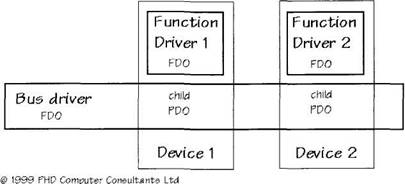
Figure 8.1 shows the situation when two devices are attached to a single bus. The bus driver has two 'child' PDOs, one for each device. A suitable function driver has been found for each device. Each function driver has created an FDO to store information about its device.
The bus driver controls three different device objects. Each child PDO receives requests from the function driver layered about it. In addition, the bus driver has an FDO of its own which it uses to store information about the whole bus. A bus driver might handle child PDO requests by sending them to its FDO for processing.
Just to reiterate, each function driver knows how to control the functions in a device. However, a function driver usually uses the facilities of its underlying bus driver to talk to its device.
Even a virtual device driver like Wdm1 has a device stack. Wdm1 is a function driver and so its device object is an FDO. There is a bus driver underneath Wdm1, the system unknown driver. the unknown bus driver makes a PDO to represent each Wdm1 device. The Unknown driver does some important jobs, even though it does not correspond to a hardware bus. The following chapter describes the jobs that even a minimal bus driver like Unknown must do.
Figure 8.1 A bus driver, two devices, and their function drivers

Device Stacks
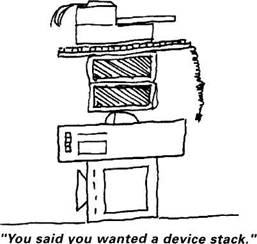
When one driver layers its device over another, it forms a device stack. Each device in the stack usually plays some part in processing user requests.
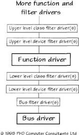
Figure 8.2 shows a generic device stack. A bus driver is always at the bottom of the stack. One or more function drivers do the main device control functions.
Filter drivers are used to modify the behavior of standard device drivers. Rather than rewrite a whole bus or class driver, a filter driver modifies its actions in the area of interest. As the figure shows, there are various types of filter driver. A bus filter driver acts on all devices that attach to a particular bus driver. Class filter drivers are installed in the stack for each device of the specified class. Finally, a device filter driver is installed for one particular device. Lower-level filter drivers are below the function driver, while upper-level drivers are above the function driver in the stack.
Filter drivers are only installed when a device is first installed, so they cannot be inserted once a device stack has been built.

Figure 8.2 Bus, function, and filter drivers

Monolithic and Layered Drivers
When a standard keyboard is found, Windows loads the appropriate driver. This talks directly to the keyboard through its controller electronics. The keyboard driver is described as monolithic because it takes over all the processing required to handle the keyboard (i.e., it does not use other drivers to do its job).
In contrast, USB drivers use a layered approach. To use a USB keyboard, the keyboard driver uses the services of the USB class drivers.
As shown in Chapter 21, the USB class drivers expose an upper edge that drivers higher than it must use. Such drivers can issue USB Request Blocks (URBs), which transmit or receive information from a USB device. The keyboard driver does not care how the USB class drivers do their job.
The situation for the USB class drivers themselves is probably slightly different[18]. They are told where the USB bus controller electronics live, and they make use of the services of the PCI bus driver. However, I suspect that the USB class drivers talk directly to their own hardware. Asking the PCI bus driver to write or read memory would be too slow.
A different approach would have been to let each USB driver talk directly to the USB hardware in a monolithic driver. This would lead to two problems. The first is that each USB driver would need a large amount of code. Duplicating this code would waste memory and writing large drivers is decidedly error prone. The second problem is almost of more significance: how would all these different drivers coordinate their activities? The answer is, of course, with difficulty. Using different layers of drivers solves both these problems.
- Overview of Configuration Files
- Overview
- 2.2 Overview of Linkers and the Linking Process
- Lesson 1: Creating and Customizing the Operating System Design
- Operating System Design Overview
- OS Design Property Pages
- Advanced OS Design Configurations
- Overview of Fedora Printing
- 1.5. DESIGN ISSUES
- 2.5.2. Design Issues
- 4.1.3. Design Issues for Threads Packages
- 4.3.2. Design Issues for Processor Allocation Algorithms


