Книга: Real-Time Concepts for Embedded Systems
11.5 A Model for Implementing the Soft-Timer Handling Facility
The functions performed by the soft-timer facility, called the timer facility from now on, include:
· allowing applications to start a timer,
· allowing applications to stop or cancel a previously installed timer, and
· internally maintaining the application timers.
The soft-timer facility is comprised of two components: one component lives within the timer tick ISR and the other component lives in the context of a task.
This approach is used for several reasons. If all of the soft-timer processing is done with the ISR and if the work spans multiple ticks (i.e., if the timer tick handler does not complete work before the next clock tick arrives), the system clock might appear to drift as seen by the software that tracks time. Worse, the timer tick events might be lost. Therefore, the timer tick handler must be short and must be conducting the least amount of work possible. Processing of expired soft timers is delayed into a dedicated processing task because applications using soft timers can tolerate a bounded timer inaccuracy. The bounded timer inaccuracy refers to the imprecision the timer may take on any value. This value is guaranteed to be within a specific range.
Therefore, a workable model for implementing a soft-timer handling facility is to create a dedicated processing task and call it a worker task, in conjunction with its counter part that is part of the system timer ISR. The ISR counterpart is given a fictitious name of ISR_timeout_fn for this discussion.
The system timer chip is programmed with a particular interrupt rate, which must accommodate various aspects of the system operation. The associated timer tick granularity is typically much smaller than the granularity required by the application-level soft timers. The ISR_timeout_fn function must work with this value and notify the worker task appropriately.

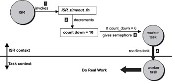
Figure 11.4: A model for soft-timer handling facility.
In the following example, assume that an application requires three soft timers. The timeout values equal 200ms, 300ms, and 500ms. The least common denominator is 100ms. If each hardware timer tick represents 10ms, then 100ms translates into a countdown value of 10. The ISR_timeout_fn keeps track of this countdown value and decrements it by one during each invocation. The ISR_timeout_fn notifies the worker task by a "give" operation on the worker task's semaphore after the countdown value reaches zero, effectively allowing the task to be scheduled for execution. The ISR_timeout_fn then reinitializes the countdown value back to 10. This concept is illustrated in Figure 11.4.
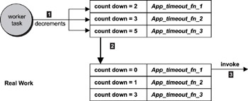
In the ISR-to-processing-task model, the worker task must maintain an application-level, timer-countdown table based on 100ms granularity. In this example, the timer table has three countdown values: 2, 3, and 5 representing the 200ms, 300ms, and the 500ms application-requested timers. An application-installed, timer-expiration function is associated with each timer. This concept is illustrated in Figure 11.5.

Figure 11.5: Servicing the timer interrupt in the task context.
The three soft timers, which are simply called timers unless specified otherwise, are decremented by the worker task each time it runs. When the counter reaches zero, the application timer has expired. In this example, the 200ms timer and the associated function App_timeout_fn_1, which the application installs, is invoked. As shown in Figures 11.4 and 11.5, a single ISR-level timer drives three application timers at the task-level, providing a good reason why these timers are called soft timers. The decrease in the number of ISR timers installed improves the overall system performance.
These application-installed timers are called soft timers because processing is not synchronized with the hardware timer tick. It is a good idea to explore this concept further by examining possible delays that can occur along the delivery path of the timer tick.
- Forced writes - палка о двух концах
- Forced Writes
- 4.4.4 The Dispatcher
- About the author
- Chapter 7. The state machine
- Chapter 15. Graphical User Interfaces for Iptables
- Appendix E. Other resources and links
- What NAT is used for and basic terms and expressions
- Example NAT machine in theory
- Information request
- SCTP Generic header format
- The final stage of our NAT machine


