Книга: Advanced PIC Microcontroller Projects in C
Project Hardware
Project Hardware
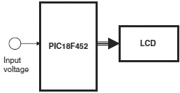
Figure 6.38 shows the block diagram of the project. The microcontroller reads the analog voltage, converts it to digital, formats it, and then displays it on the LCD.

Figure 6.38: Block diagram of the project
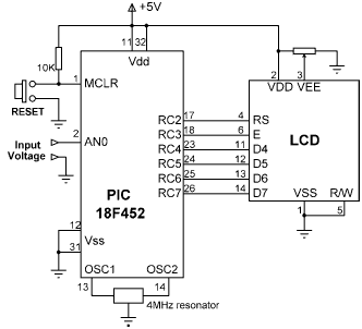
The circuit diagram of the project is shown in Figure 6.39. The voltage to be measured (between 0 and 5V) is applied to port AN0 where this port is configured as an analog input in software. The LCD is connected to PORTC of the microcontroller as in the default four-wire connection. A potentiometer is used to adjust the contrast of the LCD display.

Figure 6.39: Circuit diagram of the project
Оглавление статьи/книги


