Книга: Real-Time Concepts for Embedded Systems
3.3.1 Executing from ROM Using RAM for Data
3.3.1 Executing from ROM Using RAM for Data
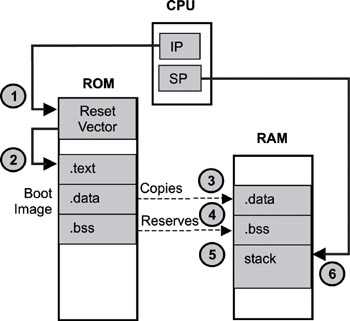
Some embedded devices have such limited memory resources that the program image executes directly out of the ROM. Sometimes the board vendor provides the boot ROM, and the code in the boot ROM does not copy instructions out to RAM for execution. In these cases, however, the data sections must still reside in RAM. Figure 3.3 shows this boot scenario.

Figure 3.3: Boot sequence for an image running from ROM.
Two CPU registers are of concern: the Instruction Pointer (IP) register and the Stack Pointer (SP) register. The IP points to the next instruction (code in the.text section) that the CPU must execute, while the SP points to the next free address in the stack. The C programming language uses the stack to pass function parameters during function invocation. The stack is created from a space in RAM, and the system stack pointer registers must be set appropriately at start up.
The boot sequence for an image running from ROM is as follows:
1. The CPU’s IP is hardwired to execute the first instruction in memory (the reset vector).
2. The reset vector jumps to the first instruction of the.text section of the boot image. The.text section remains in ROM; the CPU uses the IP to execute.text. The code initializes the memory system, including the RAM.
3. The.data section of the boot image is copied into RAM because it is both readable and writeable.
4. Space is reserved in RAM for the.bss section of the boot image because it is both readable and writeable. There is nothing to transfer because the content for the.bss section is empty.
5. Stack space is reserved in RAM.
6. The CPU’s SP register is set to point to the beginning of the newly created stack. At this point, the boot completes. The CPU continues to execute the code in the.text section until it is complete or until the system is shut down.
Note that the boot image is not in the ELF format but contains binary machine code ready for execution. The boot image is created in the ELF format. The EEPROM programmer software, however, removes the ELF-specific data, such as the program header table and the section header table, when programming the boot image into the ROM, so that it is ready for execution upon processor reset.
The boot image needs to keep internal information in its program, which is critical to initializing the data sections, because the section header table is not present. As shown in Figure 3.3, the.data section is copied into RAM in its entirety. Therefore, the boot image must know the starting address of its data section and how big the data section is. One approach to this issue is to insert two special labels into the.data section: one label placed at the section’s beginning and the other placed at the end. Special assembly code is written to retrieve the addresses of these labels. These are the load addresses of the labels. The linker reference manual should contain the specific program code syntax and link commander file syntax used for retrieving the load address of a symbol. The difference between these two addresses is the size of the section. A similar approach is taken for the.bss section.
If the.text section is copied into RAM, two dummy functions can be defined. These dummy functions do nothing other than return from function. One function is placed at the beginning of the.text section, while the other is placed at the end. This reason is one why an embedded developer might create custom sections and instruct the linker on where to place a section, as well as how to combine the various sections into a single output section through the linker command file.
- Forced writes - палка о двух концах
- Информация заголовочной страницы (Database header)
- Database dialect
- Forced Writes
- Инструкция INSERT INTO ... FROM ... UNION ...
- DATABASE CACHE SIZE
- Chapter 15. Graphical User Interfaces for Iptables
- What NAT is used for and basic terms and expressions
- Caveats using NAT
- Parameter problem
- Using Double Quotes to Resolve Variables in Strings with Embedded Spaces
- Information request


