Книга: Real-Time Concepts for Embedded Systems
13.2.2 An Example of malloc and free
13.2.2 An Example of malloc and free
The following is an example implementation of malloc's allocation algorithm for an embedded system. A static array of integers, called the allocation array, is used to implement the allocation map. The main purpose of the allocation array is to decide if neighboring free blocks can be merged to form a larger free block. Each entry in this array represents a corresponding fixed-size block of memory. In this sense, this array is similar to the map shown in Figure 13.2, but this one uses a different encoding scheme. The number of entries contained in the array is the number of fixed-size blocks available in the managed memory area. For example, 1MB of memory can be divided into 32,768 32-byte blocks. Therefore, in this case, the array has 32,768 entries.
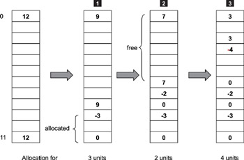
To simplify the example for better understanding of the algorithms involved, just 12 units of memory are used. Figure 13.3 shows the example allocation array.

Figure 13.3: Static array implementation of the allocation map.
In Figure 13.3, let the allocation-array index start at 0. Before any memory has been allocated, one large free block is present, which consists of all 12 units of available memory. The allocation array uses a simple encoding scheme to keep track of allocated and free blocks of memory. To indicate a range of contiguous free blocks, a positive number is placed in the first and last entry representing the range. This number is equal to the number of free blocks in the range. For example, in the first array shown on the left, the number of free units (12 in this case) is placed in the entries at index 0 and index 11.
Placing a negative number in the first entry and a zero in the last entry indicates a range of allocated blocks. The number placed in the first entry is equal to -1 times the number of allocated blocks.
In this example, the first allocation request is for three units. The array labeled 1 in Figure 13.3 represents the state of the allocation array after this first allocation request is made. The value of -3 at index 9 and the value of 0 at index 11 marks the range of the allocated block. The size of the free block is now reduced to nine. Step 3 in Figure 13.3 shows the state of the allocation array at the completion of three allocation requests. This array arrangement and the marking of allocated blocks simplify the merging operation that takes place during the free operation, as explained later in this chapter.
Not only does this allocation array indicate which blocks are free, but it also implicitly indicates the starting address of each block, because a simple relationship exists between array indices and starting addresses, as shown
starting address = offset + unit_size*index
When allocating a block of memory, malloc uses this formula to calculate the starting address of the block. For example, in Figure 13.3, the first allocation for three units begins at index 9. If the offset in the formula is 0x10000 and the unit size is 0x20 (32 decimal), the address returned for index 9 is
0x10000 + 0x20*9 = 0x10120
- 3.2.1. Библиотечные вызовы: malloc(), calloc(), realloc(), free()
- 3.2.1.6. Подведение итогов из GNU Coding Standards
- 3.2.1.3. Освобождение памяти: free()
- Разработка приложений баз данных InterBase на Borland Delphi
- Open Source Insight and Discussion
- Introduction to Microprocessors and Microcontrollers
- Chapter 6. Traversing of tables and chains
- Chapter 8. Saving and restoring large rule-sets
- Chapter 11. Iptables targets and jumps
- Chapter 5 Installing and Configuring VirtualCenter 2.0
- Chapter 14. Example scripts
- Chapter 16. Commercial products based on Linux, iptables and netfilter


