Книга: Writing Windows WDM Device Drivers
Types of Device Driver
Разделы на этой странице:
Types of Device Driver
This section gives a picture of where device drivers fit in the general scheme of things, and the different types of driver that exist.
Windows Overview
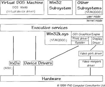
Figure 2.2 shows a general driver schematic of Windows. User mode programs usually run in Win32 or the Virtual DOS Machine provided for DOS and Win 16 applications. NT and W2000 also support other subsystems, such as OS/2 and Posix, but I think these are little used. Most user mode calls end up as requests to kernel mode.
The kernel mode executive services do any security and parameter checking that is appropriate before passing the request onto other parts of the kernel. In NT and W2000, a portion of the Win32 functionality is implemented in the kernel to achieve good performance. In particular, this Win32k.sys driver includes the Graphics Display Interface (GDI) engine. Print and display drivers live in here; these drivers are not covered by this book. Video requests are then processed by a generic video port driver. This port driver uses video miniport drivers to talk to specific display adapters.
Windows 95 and Windows 98 use Virtual Device Drivers (VxDs) to talk to hardware. These are not covered by this book. Windows NT, Windows 2000 and Windows 98 use WDM or NT style device drivers to talk to hardware. In NT and W2000, a Hardware Abstraction Layer (HAL) provides a portable interface to actual hardware.
Figure 2.2 Windows systems
I/O Request Processing
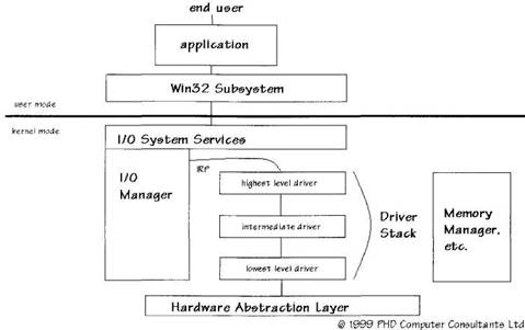
Figure 2.3 shows how an action by a user ends up being processed by device drivers. An application program makes a Win32 call for device I/O. This is received by the I/O System Services. The I/O Manager builds a suitable I/O Request Packet (IRP) out of the request.
In the simplest case, the I/O Manager just passes the IRP to one device driver. This interacts with hardware and, in due course, completes work on the IRP. The I/O Manager returns the data and results to Win32 and the user application.
It is very common now for an IRP to be processed by a stack of layered device drivers. Each driver breaks down the request into simpler requests. Highest level drivers, such as file system drivers, know how files are represented on disk, but not the details of how to get at the data. Intermediate level drivers process requests further (e.g., by breaking down a large request into a series of manageable chunks). Finally, lowest-level drivers actually interact with the hardware.
Wherever possible, drivers have been designed to be as generic as possible. For example, the SCSI port driver knows how to translate disk data requests into SCSI requests. However, it delegates the issuing of SCSI requests to SCSI miniport drivers that know how to talk to individual types of SCSI adapter.
One useful type of intermediate driver is a filter driver. A filter driver slips in between other driver layers to add functionality without effecting the higher or lower drivers. For example, a filter driver can be used to provide fault-tolerant disk access in which data is written to two separate physical disks to ensure that no data is lost.
Figure 2.3 Device driver calls
Plug and Play Device Stacks
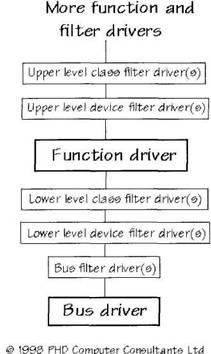
The Windows Driver Model (WDM) redefines driver layering to fit in with the Plug and Play system. A device stack represents the layers of drivers that process requests, as shown in Figure 2.4. A bus driver controls access to all devices on their bus. For example, you must use the USB bus drivers if you want to talk to a USB device.
The bus driver is responsible for enumerating its bus. This means finding all devices on the bus and detecting when devices are added or removed. The bus driver creates a Physical Device Object (PDO) to represent the device it has found. Some bus drivers simply control access to the bus; you can do what you want with the bus once you have control. In other cases, the bus driver handles all transactions on the bus for you.
A function driver that does know how to control a device's main features is layered above the bus driver. A function driver creates a Function Device Object (FDO) that is put in the device stack. In the USB case, the function driver must use the USB class driver to talk to its device. However, in other cases, once the bus driver has given the go ahead, the function driver can access hardware directly.
It is quite possible for more function drivers to be layered on top of the first function driver. An example of this is given shortly.
Various types of filter drivers can be slipped into the device stack. Bus driver filters are added above the bus driver for all devices on the bus. Class filter drivers are added for all function drivers of a specific class. Device filter drivers are added only for a particular device. Upper-level filter drivers go above the function driver, while lower-level drivers go below.
It is important to realize that user requests always enter at the top of a device stack. Suppose a user program has identified a function device to which it wants to talk. The I/O Manager ensures that all its requests are sent to the top of the device stack, so that any higher filter or function drivers get a chance to process the requests first.
Figure 2.4 Generic WDM driver stack
Standard Bus and Class Drivers
Figure 2.5 shows the main class and bus drivers that are provided with Windows. These are general purpose drivers that can act as bus drivers and as function drivers. In most cases, the main system driver is accompanied by another driver that interfaces with hardware or another class driver. These helper drivers are usually called minidrivers but can be called miniclass or miniport drivers. For example, the Human Input Device (HID) class driver uses minidrivers to talk to hardware. One minidriver is provided to talk to HID devices on the USB bus. This HID minidriver translates requests from the HID class driver into requests to the USB bus driver.
I will discuss only the HID and USB class drivers in detail. Please consult the Driver Development Kit (DDK) documentation for details of the other system class and bus drivers. Any driver that uses a bus or class driver is often called a client driver.
Figure 2.5 Bus and class drivers
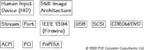
The Advanced Configuration and Power Interface (ACPI) bus driver interacts with the PC ACPI BIOS to enumerate the devices in the system and control their power use. The Peripheral Component Interconnect (PCI) bus driver enumerates and configures devices on the PCI bus. The PnPISA bus driver does a similar job for Industry Standard Architecture (ISA) devices that are configurable using Plug and Play.
The Stream class driver provides a basis for processing high bandwidth, time critical, and video and audio data. The stream class driver uses minidrivers to interface to actual hardware. Filter drivers can be written to transform data. In addition, a USB Camera helper minidriver is provided to make it easier to manage USB video and audio isochronous data streams.
The Stream class makes it easier to expose the different aspects of a piece of hardware as different subdevices. The audio Port class driver helps this further by using COM to identify the subdevices. Audio port and miniport are used to control the actual hardware.
The IEEE 1394 bus driver enumerates and controls the IEEE 1394 (Firewire) high speed bus. This bus driver uses port drivers to talk to the IEEE 1394 control electronics. IEEE 1394 client drivers issue IEEE 1394 Request Blocks (IRBs) to control their device.
The Universal Serial Bus (USB) bus driver enumerates and controls the lower-speed USB bus. Host controller drivers are provided as standard to talk to the two main types of USB host controller. USB client drivers use various IOCTLs to talk to their device via the USB class driver. The most important IOCTL lets clients issue USB Request Blocks (URBs) to control their device.
The SCSI and CDROM/DVD drivers are used to access hard disks, floppies, CDs, and DVDs. As usual, a variety of port and miniport drivers are used to talk to hardware. For example, requests to a CD-ROM on the IEEE 1394 bus would be routed to the IEEE 1394 bus driver.
The Human Input Device (HID) class driver provides an abstract view of input devices. The actual input hardware can be connected in different ways that are shielded by HID minidrivers. Quite a few HID devices are on the USB bus, so a HID minidriver for the USB bus is provided as standard. HID clients can either be user mode applications or, if need be, kernel mode drivers. Standard parsing routines are available to make sense of HID input and output reports.
Finally, the Still Image Architecture (STI) is not a driver at all, but a means of obtaining scanner and still image camera using minidrivers. STI currently supports SCSI, serial, parallel, and USB devices.
Example Driver Stack
With all these different types of drivers lurking around, it is worth while having a look at one real example to see how it all fits together. You do not need to know the detailed terminology yet.
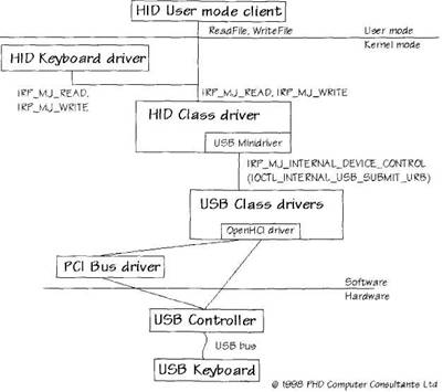
Figure 2.6 shows the hardware and software components that are involved in the handling of a HID keyboard attached to the USB bus. On power up, the PCI bus driver finds the USB controller and so loads the USB class drivers. In this case, the USB OpenHCI host controller driver is used to talk directly to the hardware.
The USB host controller electronics detects when the keyboard is plugged in. The USB root hub bus driver is informed. It tells the Plug and Play Manager that a new device has arrived. The keyboard Hardware ID is used to find the correct installation INF file. In this case, the HID class driver and its USB minidriver are loaded, along with the standard HID keyboard client driver.
The HID keyboard driver uses Read IRPs to request keyboard data. The HID class driver asks the USB minidriver to retrieve any HID input reports. The minidriver uses an Internal IOCTL to submit URBs to the USB class drivers to read data. The USB class drivers talk directly to USB host controller electronics to get any available data. The electronics finally generates the correct signals on the USB bus. These are interpreted by the USB keyboard and it returns any keypress information. The results percolate up the device stack and will eventually reach a Win32 program in message form.
Figure 2.6 also shows that a user mode HID client can access the HID keyboard using standard Win32 ReadFile and WriteFile requests.
Figure 2.6 HID USB keyboard example
- Creating and Deleting Device Objects
- Types of Kernels
- A Tour of Linux Network Devices
- Other Network Types
- Chapter 15 WdmIo and PHDIo Drivers
- Device Names
- Writing Windows WDM Device Drivers
- JDBC Туре 4 DRIVER
- Appendix C. ICMP types
- Test Driver Code
- Installing Proprietary Video Drivers
- Introduction to Serial Devices
