Книга: Writing Windows WDM Device Drivers
USB Low Level Structure
Разделы на этой странице:
USB Low Level Structure
USB Devices
USB devices can be plugged into any USB ports on a PC. Some USB devices are hubs that allow further USB devices or hubs to be connected. A hub has one upstream connection towards the PC, and multiple downstream ports. Up to 127 devices can be connected in total. A hub counts as a device.
In USB-speak, the PC is called the host. Data is always transferred between the host and a device, or vice versa. Devices never talk to each other. The PC contains the root hub (or hubs), usually with a couple of downstream ports.
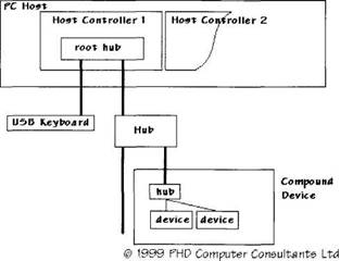
This arrangement leads to the star or branch architecture shown in Figure 20.2.
A device that does a useful job is called a function device. A USB compound device supports several functions. Internally, they consist of a hub with several downstream function devices.
Figure 20.2 shows an example USB physical layout. A USB keyboard is connected to one of a PC's USB ports. A USB hub is connected to the other PC port. The hub has two downstream ports. One is spare and the other has a compound USB device connected. Internally, the compound device has a hub and two function devices.
Figure 20.2 Example USB physical architecture

A PC has one or more USB host controllers built into it (e.g., each with two ports). There are two standard types of host controller: the USB Host Controller Interface (UHCI) and the Open Host Controller Interface (OHCI). The Windows USB class drivers have a miniclass driver for each of these controller types.
USB Signals
The USB cable has four wires. Two wires carry 5V power. Some devices may use this to power themselves, while others will be self-powered (i.e., battery or mains powered).
The other two USB wires carry the serial data. Data transfer is in one direction only at a time. Serial data is either transferred at full speed, 12 megabits per second (Mbs), or at low speed, 1.5 Mbs. All the serial data is at one of these speeds, so there is no rate conversion in hubs. A device is either a full-speed device or a low-speed device.
Note that there is no intention to uprate these communication speeds, unlike IEEE 1394. Move to IEEE 1394 if you need higher speed.
The USB protocol defines what appears on the serial bus. The host starts all transactions, but data transfer direction is switched, if necessary, during a transaction. The protocol allows devices to be plugged in at runtime and configured, and for devices to be unplugged at any time. Communication occurs only between the host and one device at a time.
Hubs repeat downstream data to all downstream ports (but not full-speed data to low-speed devices). For upstream data, hubs understand the protocol so they know which port (if any) to route upstream. Hubs do not buffer data.
Bus Signalling
The bus can be suspended by the host to reduce power, either globally or just for a specific device. If a device detects the suspended state then it must power down. The host can resume signalling on the bus to wake up all devices. Alternatively, a device can issue a remote wake-up to the host (e.g., for a telephone to indicate an incoming call).
The host can signal to a device that it should reset.
In some circumstances, communications on a pipe to a device can be stalled (e.g., if the data is corrupted). The host has to clear the problem via another pipe before normal communication can continue.
A hub detects electrically when a device is removed or plugged in, and whether it is a full-speed or low-speed device. How USB and Windows react after this is described later.
Low Level Protocol
The USB protocol defines what happens on the serial data lines. The available data transmission time — the bandwidth — is divided up into frames, each 1ms long. At full speed a frame contains a maximum of 1500 bytes and, at low speed, 187 bytes.
Frames are primarily used as a means of allocating bandwidth to the different transfers that want to occur. The regular frame timing can also be used by devices to synchronize their activities to the USB bus. Frames are of particular interest to isochronous devices and drivers.
Packets
The smallest block of data transferred on the serial lines is called a packet. A packet is sent in only one direction, either from the host or to the host.
A packet consists of synchronization signals, a Packet ID (pid), possibly some data, and some CRC check bytes. There are 10 Packet IDs in four categories:
| Token | OUT IN SOF SETUP |
| Data | DATA0 DATA1 |
| Handshake | ACK NAK STALL |
| Special | PRE |
Transactions
A transaction is a discrete interaction between the host and one device using one or more packets.
The host always starts a transaction with one of the Token type pids. A Data packet or packets may follow in either direction. Finally, a Handshake is sent back in the opposite direction to the data transfer.
The IN, OUT, and SETUP packets specify a USB address and endpoint, to specify the device and endpoint that should respond. One hundred and twenty-eight addresses are supported, with 0 being the default address on power-up or reset.
A SETUP packet includes eight data bytes to indicate what transaction is happening. USB defines standard control transactions, as described later. Other class and vendor specific SETUP control transactions are outside the basic USB spec.
The two different DATA pids are used to make it easier to detect if a complete data packet has been missed.
The ACK Handshake packet indicates that the transfer completed successfully, while NAK indicates that it did not (or that no data was available). A STALL Handshake return means that some serious error occurred in the device or endpoint, which the host must clear using another pipe.
When any of the previous packets are sent at low speed to a low-speed device, it is seen by a high-speed device as a PRE packet and so is ignored.
There are various limits on the packet size. DATA packets may be up to 1023 bytes long.
Start of Frame (SOF)
The SOF packet is sent by the host to indicate the start of a frame. This packet includes an 11-bit frame number, continuously going from 0 to 0x7FF (i.e., USBD_ISO_START_FRAME_RANGE–1) and rolling over to 0 again. SOF packets are seen by all high-speed devices. Note that SOF packets can be corrupted, as can any other packets.
Transaction Packet Structure
A control transfer involves the host sending the device a SETUP packet, zero or more DATA packets in either direction, and a Handshake.
An IN packet or an OUT packet starts all the other transfers. The definition of the device's endpoint determines whether it is an interrupt, bulk, or isochronous transfer.
The host starts Interrupt transfers regularly to see if the device endpoint has any data available. The device endpoint may return the data. Alternatively, the device might send NAK to indicate that there is no data available or that the state has not changed.
Similarly, bulk input requests may return data or NAK.
Remember that all pipes might stall.
Power
When first reset, a device can draw 100mA (milliampere) from the bus. When configured, it can draw the power it asked for, up to the maximum of 500mA. If suspended, a device may only use 500µA (microampere).
- rc.firewall.txt script structure
- The structure
- Как переносить данные через USB-брелок («флэшку»)?
- Наносится ли какой-нибудь вред USB-брелоку, когда его извлекают из разъема без использования функции безопасного отключе...
- Установка устройств с интерфейсом USB
- System Services and Runlevels
- Runlevel Definitions
- Booting into the Default Runlevel
- Booting to a Nondefault Runlevel with GRUB
- Changing Runlevels
- Troubleshooting Runlevel Problems
- Restricting Access with allow and deny


