Книга: Real-Time Concepts for Embedded Systems
15.6.1 Synchronous Activity Synchronization
Разделы на этой странице:
15.6.1 Synchronous Activity Synchronization
Multiple ways of implementing synchronous activity synchronization are available, including:
· task-to-task synchronization using binary semaphores,
· ISR-to-task synchronization using binary semaphores,
· task-to-task synchronization using event registers,
· ISR-to-task synchronization using event registers,
· ISR-to-task synchronization using counting semaphores, and
· simple rendezvous with data passing.
Task-to-Task Synchronization Using Binary Semaphores
In this design pattern, two tasks synchronize their activities using a binary semaphore, as shown in Figure 15.6. The initial value of the binary semaphore is 0. Task #2 has to wait for task #1 to reach an execution point, at which time, task #1 signals to task #2 its arrival at the execution point by giving the semaphore and changing the value of the binary semaphore to 1. At this point, depending on their execution priorities, task #2 can run if it has higher priority. The value of the binary semaphore is reset to 0 after the synchronization. In this design pattern, task #2 has execution dependency on task #1.
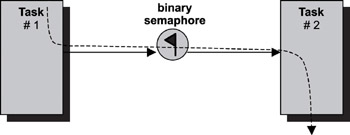
Figure 15.6: Task-to-task synchronization using binary semaphores.
ISR-to-Task Synchronization Using Binary Semaphores
In this design pattern, a task and an ISR synchronize their activities using a binary semaphore, as shown in Figure 15.7. The initial value of the binary semaphore is 0. The task has to wait for the ISR to signal the occurrence of an asynchronous event. When the event occurs and the associated ISR runs, it signals to the task by giving the semaphore and changing the value of the binary semaphore to 1. The ISR runs to completion before the task gets the chance to resume execution. The value of the binary semaphore is reset to 0 after the task resumes execution.
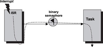
Figure 15.7: ISR-to-task synchronization using binary semaphores.
Task-to-Task Synchronization Using Event Registers
In this design pattern, two tasks synchronize their activities using an event register, as shown in Figure 15.8. The tasks agree on a bit location in the event register for signaling. In this example, the bit location is the first bit. The initial value of the event bit is 0. Task #2 has to wait for task #1 to reach an execution point. Task #1 signals to task #2 its arrival at that point by setting the event bit to 1. At this point, depending on execution priority, task #2 can run if it has higher priority. The value of the event bit is reset to 0 after synchronization.
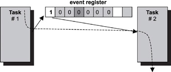
Figure 15.8: Task-to-task synchronization using event registers.
ISR-to-Task Synchronization Using Event Registers
In this design pattern, a task and an ISR synchronize their activities using an event register, as shown in Figure 15.9. The task and the ISR agree on an event bit location for signaling. In this example, the bit location is the first bit. The initial value of the event bit is 0. The task has to wait for the ISR to signal the occurrence of an asynchronous event. When the event occurs and the associated ISR runs, it signals to the task by changing the event bit to 1. The ISR runs to completion before the task gets the chance to resume execution. The value of the event bit is reset to 0 after the task resume execution.
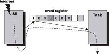
Figure 15.9: ISR-to-task synchronization using event registers.
ISR-to-Task Synchronization Using Counting Semaphores
In Figures 15.6, 15.7, 15.8, and 15.9, multiple occurrences of the same event cannot accumulate. A counting semaphore, however, is used in Figure 15.10 to accumulate event occurrences and for task signaling. The value of the counting semaphore increments by one each time the ISR gives the semaphore. Similarly, its value is decremented by one each time the task gets the semaphore. The task runs as long as the counting semaphore is non-zero.
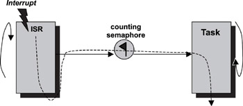
Figure 15.10: ISR-to-task synchronization using counting semaphores.
Simple Rendezvous with Data Passing
Two tasks can implement a simple rendezvous and can exchange data at the rendezvous point using two message queues, as shown in Figure 15.11. Each message queue can hold a maximum of one message. Both message queues are initially empty. When task #1 reaches the rendezvous, it puts data into message queue #2 and waits for a message to arrive on message queue #1. When task #2 reaches the rendezvous, it puts data into message queue #1 and waits for data to arrive on message queue #2. Task #1 has to wait on message queue #1 before task #2 arrives, and vice versa, thus achieving rendezvous synchronization with data passing.
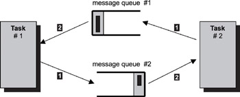
Figure 15.11: Task-to-task rendezvous using two message queues.
- 15.2.2 Activity Synchronization
- Thread Synchronization
- 3 Synchronization in Distributed Systems
- 15.4 Resource Synchronization Methods
- Monitoring User Activity on the System
- 10.4 Synchronization and Messaging Tools
- 2.2. ASYNCHRONOUS TRANSFER MODE NETWORKS
- 3.1. CLOCK SYNCHRONIZATION
- 2.2.1. What Is Asynchronous Transfer Mode?
- 3.1.3. Clock Synchronization Algorithms
- 4.5.3. Synchronous versus Asynchronous Systems
- 6.4.8. Synchronization
