Книга: Real-Time Concepts for Embedded Systems
12.2.1 Port-Mapped vs. Memory-Mapped I/O and DMA
12.2.1 Port-Mapped vs. Memory-Mapped I/O and DMA
The bottom layer contains the I/O device hardware. The I/O device hardware can range from low-bit rate serial lines to hard drives and gigabit network interface adaptors. All I/O devices must be initialized through device control registers, which are usually external to the CPU. They are located on the CPU board or in the devices themselves. During operation, the device registers are accessed again and are programmed to process data transfer requests, which is called device control. To access these devices, it is necessary for the developer to determine if the device is port mapped or memory mapped. This information determines which of two methods, port-mapped I/O or memory-mapped I/O, is deployed to access an I/O device.
When the I/O device address space is separate from the system memory address space, special processor instructions, such as the IN and OUT instructions offered by the Intel processor, are used to transfer data between the I/O device and a microprocessor register or memory.
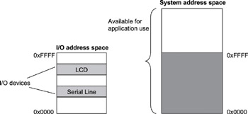
The I/O device address is referred to as the port number when specified for these special instructions. This form of I/O is called port-mapped I/O, as shown in Figure 12.2.

Figure 12.2: Port-mapped I/O.
The devices are programmed to occupy a range in the I/O address space. Each device is on a different I/O port. The I/O ports are accessed through special processor instructions, and actual physical access is accomplished through special hardware circuitry. This I/O method is also called isolated I/O because the memory space is isolated from the I/O space, thus the entire memory address space is available for application use.
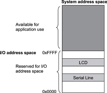
The other form of device access is memory-mapped I/O, as shown in Figure 12.3. In memory-mapped I/O, the device address is part of the system memory address space. Any machine instruction that is encoded to transfer data between a memory location and the processor or between two memory locations can potentially be used to access the I/O device. The I/O device is treated as if it were another memory location. Because the I/O address space occupies a range in the system memory address space, this region of the memory address space is not available for an application to use.

Figure 12.3: Memory-mapped I/O.
The memory-mapped I/O space does not necessarily begin at offset 0 in the system address space, as illustrated in Figure 12.3. It can be mapped anywhere inside the address space. This issue is dependent on the system implementation.
Commonly, tables describing the mapping of a device's internal registers are available in the device hardware data book. The device registers appear at different offsets in this map. Sometimes the information is presented in the 'base + offset' format. This format indicates that the addresses in the map are relative, i.e., the offset must be added to the start address of the I/O space for port-mapped I/O or the offset must be added to the base address of the system memory space for memory-mapped I/O in order to access a particular register on the device.
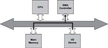
The processor has to do some work in both of these I/O methods. Data transfer between the device and the system involves transferring data between the device and the processor register and then from the processor register to memory. The transfer speed might not meet the needs of high-speed I/O devices because of the additional data copy involved. Direct memory access (DMA) chips or controllers solve this problem by allowing the device to access the memory directly without involving the processor, as shown in Figure 12.4. The processor is used to set up the DMA controller before a data transfer operation begins, but the processor is bypassed during data transfer, regardless of whether it is a read or write operation. The transfer speed depends on the transfer speed of the I/O device, the speed of the memory device, and the speed of the DMA controller.

Figure 12.4: DMA I/O.
In essence, the DMA controller provides an alternative data path between the I/O device and the main memory. The processor sets up the transfer operation by specifying the source address, the destination memory address, and the length of the transfer to the DMA controller.
- 12.2.1 Port-Mapped vs. Memory-Mapped I
- 9.3. MEMORY MANAGEMENT IN CHORUS
- 8.3.2. Memory Sharing
- 8.3.3. External Memory Managers
- 9.1.4. Kernel Abstractions
- 9.7.4. Memory Model
- Memory Analyzer (Formerly MemScope)
- Statically Reserving Physical Memory
- System Memory
- Detect Memory Leaks
- Lesson 2: Configuring Memory Mapping of a BSP
- Statically Mapped Virtual Addresses


