Книга: Distributed operating systems
2.2.5. ATM Switching
2.2.5. ATM Switching
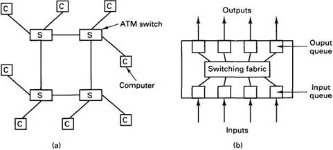
ATM networks are built up of copper or optical cables and switches. Figure 2-6(a) illustrates a network with four switches. Cells originating at any of the eight computers attached to the system can be switched to any of the other computers by traversing one or more switches. Each of these switches has four ports, each used for both input and output.
The inside of a generic switch is illustrated in Fig. 2-6(b). It has input lines and output lines and a parallel switching fabric that connects them. Because a cell has to be switched in 3 (?sec (at OC-3), and as many cells as there are input lines can arrive at once, parallel switching is essential.

Fig. 2-6. (a) An ATM switching network. (b) Inside one switch.
When a cell arrives, its VPI and VCI fields are examined. Based on these and information stored in the switch when the virtual circuit was established, the cell is routed to the correct output port. Although the standard allows cells to be dropped, it requires that those delivered must be delivered in order.
A problem arises when two cells arrive at the same time on different input lines and need to go to the same output port. Just throwing one of them away is allowed by the standard, but if your switch drops more than 1 cell in 10??, you are unlikely to sell many switches. An alternative scheme is to pick one of them at random and forward it, holding the other cell until later. In the next round, this algorithm is applied again. If two ports each have streams of cells for the same destination, substantial input queues will build up, blocking other cells behind them that want to go to output ports that are free. This problem is known as head-of-line blocking.
A different switch design copies the cell into a queue associated with the output buffer and lets it wait there, instead of keeping it in the input buffer. This approach eliminates head-of-line blocking and gives better performance. It is also possible for a switch to have a pool of buffers that can be used for both input and output buffering. Still another possibility is to buffer on the input side, but allow the second or third cell in line to be switched, even if the first one cannot be.
Many other switch designs have been proposed and tried. These include time division switches using shared memory, buses or rings, as well as space division switches with one or more paths between each input and each output.
Some of these switches are discussed in (Ahmadi and Denzel, 1989; Anderson et al., 1993; Gopal et al., 1992; Pattavina, 1993; Rooholamini et al., 1994; and Zegura, 1993).


