Новые книги
Глава 5. Ethernet/IEEE 802.3
Глава 5. Ethernet/IEEE 802.3
Основы технологии
Ethernet был разработан Исследовательским центром в Пало Альто (PARC) корпорации Xerox в 1970-м году. Ethernet стал основой для спецификации IEEE 802.3, которая появилась 1980-м году. После недолгих споров компании Digital Equipment Corporation, Intel Corporation и Xerox Corporation совместно разработали и приняли спецификацию (Version 2.0), которая была частично совместима с 802.3. На сегодняшний день Ethernet и IEEE 802.3 являются наиболее распространенными протоколами локальных вычислительных сетей (ЛВС). Сегодня термин Ethernet чаще всего используется для описания всех ЛВС работающих по принципу множественный доступ с обнаружением несущей (carrier sense multiple access/collision detection (CSMA/CD)), которые соотвествуют Ethernet, включая IEEE 802.3.
Когда Ethernet был разработан, он должен был заполнить нишу между глобальными сетями, низкоскоростными сетями и специализированными сетями компьтерных центров, которые работали на высокой скрости, но очень органиченном расстоянии. Ethernet хорошо подходит для приложений где локальные коммуникации должны выдерживать высокие нагрузки при высоких скоростях в пиках.
Сравнение Ethernet и IEEE 802.3
Ethernet and IEEE 802.3 specify similar technologies. Both are CSMA/CD LANs. Stations on a CSMA/CD LAN can access the network at any time. Before sending data, CSMA/CD stations "listen" to the network to see if it is already in use. If it is, the station wishing to transmit waits. If the network is not in use, the station transmits. A collision occurs when two stations listen for network traffic, "hear" none, and transmit simultaneously. In this case, both transmissions are damaged, and the stations must retransmit at some later time. Backoff algorithms determine when the colliding stations retransmit. CSMA/CD stations can detect collisions, so they know when they must retransmit.
Both Ethernet and IEEE 802.3 LANs are broadcast networks. In other words, all stations see all frames, regardless of whether they represent an intended destination. Each station must examine received frames to determine if the station is a destination. If so, the frame is passed to a higher protocol layer for appropriate processing.
Differences between Ethernet and IEEE 802.3 LANs are subtle. Ethernet provides services corresponding to Layers 1 and 2 of the OSI reference model, while IEEE 802.3 specifies the physical layer (Layer 1) and the channel-access portion of the link layer (Layer 2), but does not define a logical link control protocol. Both Ethernet and IEEE 802.3 are implemented in hardware. Typically, the physical manifestation of these protocols is either an interface card in a host computer or circuitry on a primary circuit board within a host computer.
Физическое подключение
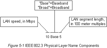
IEEE 802.3 specifies several different physical layers, whereas Ethernet defines only one. Each IEEE 802.3 physical layer protocol has a name that summarizes its characteristics. The coded components of an IEEE 802.3 physical-layer name are shown in Figure 5-1.
Figure 5-1 : IEEE 802.3 Physical-Layer Name Components

A summary of Ethernet Version 2 and IEEE 802.3 characteristics appears in Table 5-1.
| Характеристики | Ethernet | IEEE 802.3 | ||||
|---|---|---|---|---|---|---|
| 10Base5 | 10Base2 | 1Base5 | 10BaseT | 10Broad36 | ||
| Скорость, Mbps | 10 | 10 | 10 | 1 | 10 | 10 |
| Метод передачи | Baseband | Baseband | Baseband | Baseband | Baseband | Broadband |
| Макс. длина сегмента, м | 500 | 500 | 185 | 250 | 100 | 1800 |
| Среда передачи | 50-Ом коаксиал (толстый) | 50-Ом коаксиал (толстый) | 50-Ом коаксиал (тонкий) | неэкр. витая пара | неэкр. витая пара | 75-ohm coax |
| Топология | Шина | Шина | Шина | Звезда | Звезда | Шина |
Table 5-1 Ethernet Version 2 and IEEE 802.3 Physical
Characteristics
Ethernet is most similar to IEEE 802.3 10Base5. Both of these protocols specify a bus topology network with a connecting cable between the end stations and the actual network medium. In the case of Ethernet, that cable is called a transceiver cable. The transceiver cable connects to a transceiver device attached to the physical network medium. The IEEE 802.3 configuration is much the same, except that the connecting cable is referred to as an attachment unit interface (AUI), and the transceiver is called a medium attachment unit (MAU). In both cases, the connecting cable attaches to an interface board (or interface circuitry) within the end station.
Форматы блоков
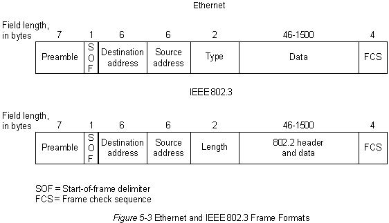
Ethernet and IEEE 802.3 frame formats are shown in Figure 5-2.

Both Ethernet and IEEE 802.3 frames begin with an alternating pattern of ones and zeros called a preamble. The preamble tells receiving stations that a frame is coming.
The byte before the destination address in both an Ethernet and a IEEE 802.3 frame is a start-of-frame (SOF) delimiter. This byte ends with two consecutive one bits, which serve to synchronize the frame reception portions of all stations on the LAN.
Immediately following the preamble in both Ethernet and IEEE 802.3 LANs are the destination and source address fields. Both Ethernet and IEEE 802.3 addresses are 6 bytes long. Addresses are contained in hardware on the Ethernet and IEEE 802.3 interface cards. The first 3 bytes of the addresses are specified by the IEEE on a vendor-dependent basis, while the last 3 bytes are specified by the Ethernet or IEEE 802.3 vendor. The source address is always a unicast (single node) address, while the destination address may be unicast, multicast (group), or broadcast (all nodes).
In Ethernet frames, the 2-byte field following the source address is a type field. This field specifies the upper-layer protocol to receive the data after Ethernet processing is complete.
In IEEE 802.3 frames, the 2-byte field following the source address is a length field, which indicates the number of bytes of data that follow this field and precede the frame check sequence (FCS) field.
Following the type/length field is the actual data contained in the frame. After physical-layer and link-layer processing is complete, this data will eventually be sent to an upper-layer protocol. In the case of Ethernet, the upper-layer protocol is identified in the type field. In the case of IEEE 802.3, the upper-layer protocol must be defined within the data portion of the frame, if at all. If data in the frame is insufficient to fill the frame to its minimum 64-byte size, padding bytes are inserted to ensure at least a 64-byte frame.
After the data field is a 4-byte FCS field containing a cyclic redundancy check (CRC) value. The CRC is created by the sending device and recalculated by the receiving device to check for damage that might have occurred to the frame in transit.
[Назад] [Содержание] [Вперед]

