Книга: Writing Windows WDM Device Drivers
Upper Edges
Разделы на этой странице:
Upper Edges
This section uses a full example to illustrate two points. First, it shows how I/O requests are handled by a real driver stack. Second, it shows how drivers can have an upper edge that is different from that provided by lower layers.
USB Keyboard Example
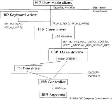
Figure 8.7 shows how a USB keyboard might be used. A USB keyboard must be accessed via the HID class driver. The figure shows how two possible HID clients talk to the keyboard.
The items in this figure are not discussed in detail. The chapters on USB and HID will explain all. The major information flows are of concern just now.
The USB keyboard driver is a kernel mode HID client that sends requests to the HID class driver in the form of standard IRP_MJ_READ and IRP_MJ_WRITE IRPs. These must be in the right format to be recognized by the HID class driver. Alternatively, a user mode HID application can access the HID keyboard directly (rather than by waiting for standard Windows character messages). It does this using the Win32 ReadFile and WriteFile routines. These calls appear to the HID class driver as IRP_MJ_READ and IRP_MJ_WRITE IRPs. Again, these requests must be in the correct HID format.
Internally, the HID class driver uses one of its minidrivers to talk to the lower drivers. In this case, it is using its USB minidriver to talk to the top of the USB stack. Although it is not shown on the diagram, the main HID class driver actually uses Internal IOCTLs to request I/O from a minidriver.
The HID USB minidriver generates Internal IOCTLs to use the services of the USB class drivers. The most common Internal IOCTL has a control code of IOCTL_INTERNAL_USB_SUBMIT_URB. This submits a USB Request Block (URB) to the USB class driver. To get some input data, the minidriver will almost certainly use the URB_FUNCTION_BULK_OR_INTERRUPT_TRANSFER function code within a URB.
As mentioned before, the USB class drivers are layered internally. In this case, the diagram shows that the OpenHCI USB host controller driver is in use. The OpenHCI driver will make some use of its lower driver, the PCI bus driver. However, it will do most of its work by talking directly to the OpenHCI USB Controller hardware. It will read and write memory and controller registers. It will almost certainly handle interrupts and use DMA to transfer information.
The USB controller hardware itself is responsible for the very last stage of the keyboard I/O request handling. It generates the appropriate signals on the USB bus, according to the instructions given to it by the USB class drivers. The USB keyboard understands these signals and responds according to its specification.
When a key is pressed on the keyboard, information percolates its way back up through the chain of drivers, ending up at one of the client drivers as a keypress input report.
Figure 8.7 HID USB Keyboard I/O Request handling

Functional and Physical Device Objects
Just to complicate matters, the previous example does not involve just one device stack. Instead, there are actually four, as shown in Table 8.3.
A device stack must always end at a Physical Device Object (PDO). Each bus driver creates a PDO for each device it finds.
1. Starting from the HID Keyboard driver's FDO, going down the stack, there is an FDO created by the HID class driver and a PDO created by the USB bus driver. These three device objects are in the first device stack.
2. The DDK documentation says that the USB class drivers are layered internally, with a hub driver at the top and a host controller driver at the bottom (OpenHCI, in this case).
3. The USB host controller was originally found by the PCI bus driver. Therefore, the host controller itself has an FDO that is layered on top of a PDO created by the PCI bus driver.
4. The PCI bus was originally found by the Windows root bus driver. The final device stack therefore consists of the PCI bus FDO layered on top of the root bus PDO.
This arrangement looks complicated. However, if you are trying to use only the USB class drivers, you do not really care how they process your requests. All the details of the other device stacks are hidden from you.
Table 8.3 USB Keyboard device stacks
| Driver | Device stack |
|---|---|
| HID Keyboard driver | HID Keyboard device FDO |
| HID class device FDO | |
| PDO (created by USB hub bus driver) | |
| USB Hub USB | Hub device FDO |
| PDO (created by USB host controller bus driver) | |
| USB Host controller | USB Host Controller device FDO |
| PDO (created by PCI bus driver) | |
| PCI Adapter | PCI device FDO |
| PDO (created by root bus driver) |
Upper Edge Definitions
This example shows how several standard Windows system drivers have been used in the device stack for a USB keyboard. Each driver writer usually needs to know only the specification of the next layer down[20]. The USB Keyboard driver writer needs to understand only the HID class driver specification. Knowledge of the different USB controllers and how to use them is definitely not required.
The upper edge of a driver is the specification of how to use it. The upper edge of the HID class driver responds to standard read and write IRPs. However, the upper edge of the USB class drivers only responds to Internal IOCTL IRPs. This is a sensible option for the USB class drivers, as it is not appropriate for user mode drivers to call them directly. User mode programs could not adhere to the timing requirements of the USB class drivers.
The example also shows that the upper edge presented by a driver does not determine its lower edge. The HID class drivers accept standard read and write IRPs. However, it implements these by sending Internal IOCTLs to its own minidriver. The USB minidriver implements its upper edge by sending URBs to the USB class drivers in its own Internal IOCTLs.
Thus, you have to look at some of the earlier example figures with care. Figure 8.5 shows function, filter, and bus drivers in a smooth hierarchy. In real life, the chain of events is much more complicated, as I/O requests are processed by several drivers.
A filter driver must have the same upper and lower edge because it must slip into the stack without affecting other drivers. A filter can modify or inspect the requests in which it is interested. However, all other requests must be passed down the stack unmodified. It is possible for a filter driver to perform some extra checking, which will mean that some IRPs are never passed down. However, it is vital that user mode applications or higher-level drivers can continue to function normally.


